Building an S-Band Antenna for the HackRF
Mario Filippi, a regular contributor to our blog and to the SDR community recently wrote in with an article showing how he built an S-Band (2 – 4 GHz) antenna for use with the HackRF. Of course the antenna can be used with any other SDR that can receive in this range, or with an RTL-SDR and downconverter. We post his article below.
S -Band Antenna for use with the HackRF One
Author: Mario Filippi, N2HUN
Ever since purchasing a HackRF One, which receives from 1 MHz – 6.0 GHz I’ve always wanted to explore the world above 1 Gig, specifically the 2.0 – 2.7 GHz portion of the S-band. This portion of the band is populated with satellite communications, ISM, amateur radio, and wireless networks. A good, homebrew antenna for S-band was needed, so with parts mostly from the junk box, a 2250 MHz S-band right hand circularly polarized omni-directional antenna was built. Below is a step by step tutorial on building this antenna. Plans were from UHF-Satcom’s site.

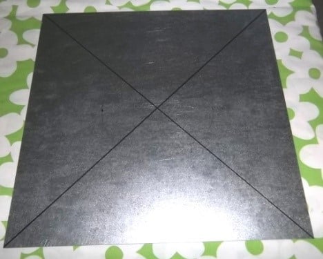
Step 1: Take a 12” x 12” galvanized plate a mark with diagonal lines to find the center.
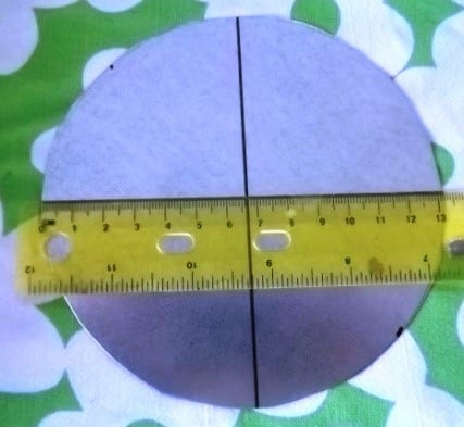
Step 2: Using a scribe, trace a 130 mm diameter circular pattern onto the plate.

Step 3: Cut out the circle with tin snips.

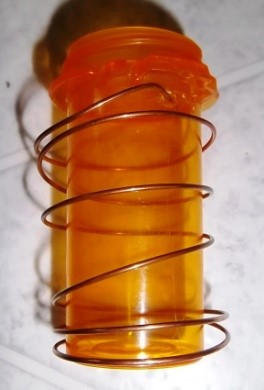
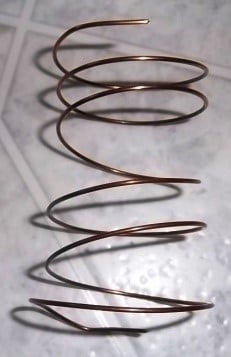
Step 4: For the coil, solid copper antenna wire is used and turned around a 31 mm diameter pill bottle, resulting in a coil approximately 40 mm diameter.
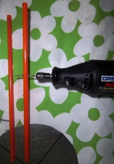
Step 5: To space the turns 27 mm apart two heavy plastic drinking straws are marked at 27 mm intervals.

Step 6: Drill holes at each 27 mm mark.
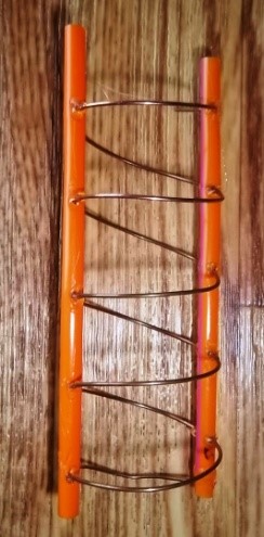
Step 7: Thread the coil through the two straws and allow it to sit for a few days to get into shape.
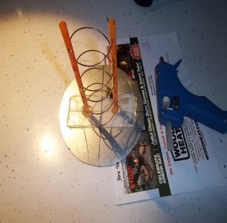
Step 8: A 2mm thick Plexiglass™ piece was marked so each straw would be 40 mm apart, then the bottoms of each straw were set in place with gobs of hot glue. Coil turns were hot glued at straw holes.

Step 9: Plexiglass™ piece and straws were hot glued to the 130 mm ground plane and a hole was drilled for an F connector later on. Coil was soldered at bottom to center pin of F connector.
Step 10: Add a coat of paint to make it look a lot better! Attach the antenna to a gooseneck suction cup mount with Velcro®. Mount on an outside window, and it is now ready for action! RG/6 coax was used.

Note that the dimensions of the coil were approximate to the dimensions specified in the UHF-Satcom plans. Since this antenna was for receive only, I did not sweat the measurement details. Hot glue was used since this was a prototype to be used only on occasion and not when the weather was inclement. The omni-directional design was chosen instead of the LHCP/satellite dish combo (both plans are outlined in the UHF-Satcom site) because I wanted to receive signals from all directions. And since the HackRF One has a built-in preamplifier, an outboard in-line filter was not used.
This may not be the best or only way to construct an S-band antenna; surely other more mechanically/electronically gifted individuals will do a much better job. Initial testing shows that the little antenna, when adjusted in different directions, is picking up actual signals in this portion of the band. You can test that by looking at a signal on the waterfall, then disconnecting the antenna; if the signal remains then you may have a spurious signal from the receiver. I hope this article encourages others to look above 1 Gig mark on the spectrum. You don’t need a HackRF One necessarily as most SDR dongles cover up to at least 1.6 GHz. With a dongle you can explore other bands such as the L-band ( 1 – 2 GHz) using the right antenna and preamp; check previous articles in this website (www.rtl-sdr.com) for details. A hearty thanks to the folks at UHF-Satcom for their S-band antenna plans and information.


