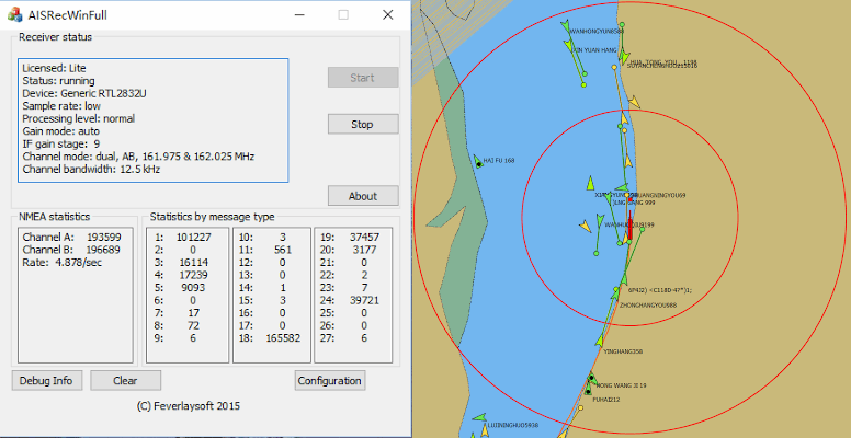
Last time we tried AISRec we found its performance to be very good, with it decoding more messages than other software we tried. The new version includes the following updates:
Added auto detection of devices when devices are plugged in.
Added the support for airspy. Allow selection of devices by serial number for rtlsdr dongles.
Added AISRec core 3.0. The new core is 2x faster than AISRec core 2.0.
Added one embedded multi-user TCP server. Any client works with AISRec should implement auto reconnection.
Added auto display of local IP for the TCP server.
Added one output to one serial port.
Added interactive changes of gain parameters for devices.
A few changes on GUI.
Added an icon for GUI. Users should reset the windows icon buffer to allow the display of the new icon.
In addition, while AISRec hopes to be commercial software one day, at the moment they are currently offering free registration. See their FAQ for information on registering for free.
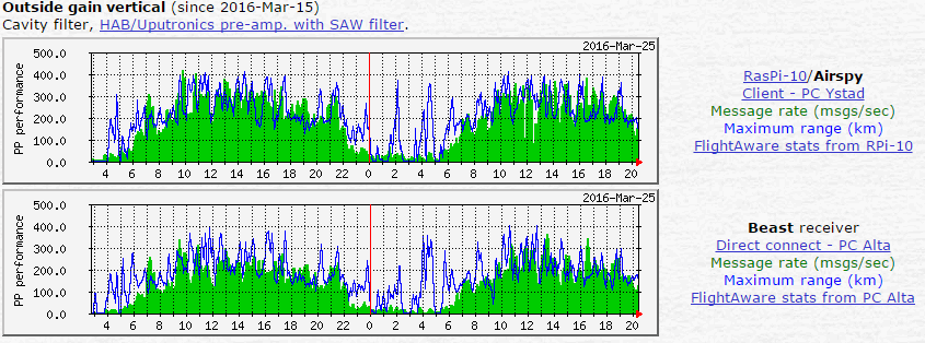
Unsurprisingly the results clearly show that the Airspy receives ADS-B signals significantly better than the RTL-SDR. However, what comes as a surprise is that it is actually appears to be outperforming the dedicated Beast receiver. In the tests with the outside vertical antenna, the Airspy running on a Raspberry Pi appears to receive a significant higher number of messages and also sees planes out to a further range.
Not too long ago the Airspy team released their ADS-B software for the Raspberry Pi 2. They write that this software uses the full 10 MHz bandwidth and can even decode messages that are overlapping one another. We’ve also been told by the Airspy team that the Airspy is already in professional use as an ADS-B receiver amongst several small airports.
In the future we hope to compare the Airspy against the RTL-SDR on ADS-B reception ourselves, and also compare it against the 8 MHz bandwidth SDRplay whose development team have also recently released a new ADS-B decoder, as well as the recently released FlightAware ADS-B Prostick RTL-SDR.
Software defined radio's can easily be used a very wideband spectrum analyzers by quickly stepping through the spectrum at the largest stable bandwidth supported. The RTL-SDR has had this functionality for some time now through software such as rtl_power and RTL Scanner.
Now Youssef, co-creator of the Airspy and programmer of SDR# has released a similar program for the Airspy called Spectrum Spy. The software comes bundled with the latest SDR# download which can be obtained from airspy.com.
The Airspy is a $199 USD software defined radio with a similar tuning range to the RTL-SDR, but it is significantly better with its 12-bit ADC and up to 10 MHz of instantaneous bandwidth. We review the Airspy, SDRplay RSP and HackRF in this post. With its large instantaneous bandwidth and fast retuning speed the Airspy makes an excellent spectrum analyzer that refreshes very quickly.
Youssef stresses that the software is still in proof of concept stages, and various features are still to be added in the future. He writes:
A new utility app is available for download with the standard SDR# package. It allows the visualization of larger frequency spans by exploiting Airspy's fast frequency tuning capability. The scanning speed is comparable to real spectrum analyzers (may be faster even!) The project is still in a PoC state, but the basic functionality provided is fully operational.
It all started when some customer wanted an example code to implement their own SA using Airspy, so I did more than a code snippet. I hope you enjoy!
We tested the Spectrum Spy software on several bands, and recorded short videos shown below to show how fast it is.
20 MHz Bandwidth Mobile Phone Band
50 MHz BCFM Band
100 MHz Bandwidth Mobile Phone Band
Includes the uplink and downlink portions. We used our mobile phone to make a call and you can see the uplink at 895 MHz.
1 GHz Full Spectrum
Tweeted Photos
Over on Twitter @uhf_satcom has also been testing out Spectrum Spy and has got some good shots of Ku and L-band satellite bands.
@Sdrsharp Spectrum Spy + AirSpy SDR on IF of Ku-Band LNB pointed at 36E - really useful tool for satellite nerds! pic.twitter.com/dYwVJVIOz1
Last week we posted how programmer Jonti had successfully implemented a C-Band AERO decoder into his JAERO software. C-band AERO signals are the earth downlink portion of AERO. Planes transmit data upwards towards the satellites and then the Inmarsat C-band transmitter re-transmits the information back to a basestation on earth. This is different to the L-band AERO signals which are signals transmitted from the satellites to the aircraft. C-band signals are interesting because they contain plane position info, and so can be used to track aircraft much like what is done with ADS-B reception, but over a much larger area. However, C-Band signals are much more difficult to receive as they are at 3.616 GHz and require a 1.8m or larger satellite dish.
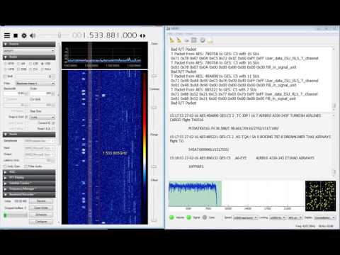
Over on YouTube user AceBlaggard has uploaded a video showing an example of C-Band signals being received with an Airspy SDR and being decoded with the new version of JAERO. About the hardware used AceBlaggard writes:
Hardware is a 1.8M PF dish and Titanium Satellite C1 PLL LNB feeding a Prof-Tuner 7301 sat card which loops out to an Airspy SDR.
IMPORTANT NOTE: Please note that this review is now out of date as the SDRplay RSP line has received significant improvements to their hardware and Airspy have brought out a new SDR that is much better at HF.
Overall it is now difficult to pick a winner between Airspy and SDRplay products. However, our preference is the Airspy HF+ Discovery for HF signals, and the SDRplay RSP1A for generic wideband wide frequency range receiving.
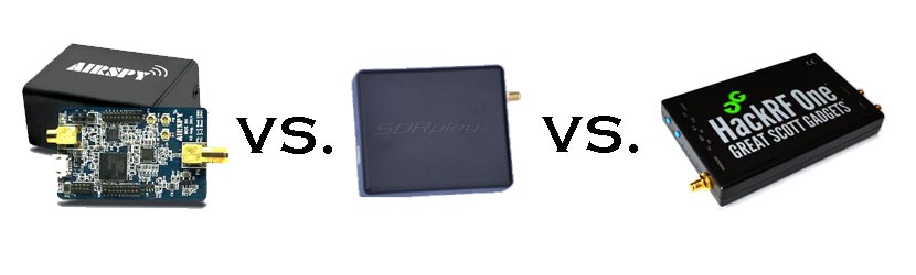
When people consider upgrading from the RTL-SDR, there are three mid priced software defined radios that come to most peoples minds: The Airspy (store), the SDRplay RSP (store) and the HackRF (store). These three are all in the price range of $150 to $300 USD. In this post we will review the Airspy, review the SDRplay RSP and review the HackRF and compare them against each other on various tests.
Note that this is a very long review. If you don't want to read all of this very long post then just scroll down to the conclusions at the end.
What makes a good SDR?
In this review we will only consider RX performance. So first we will review some terminology, features and specifications that are required for a good RX SDR.
SNR - When receiving a signal the main metric we want to measure is the "Signal to Noise" (SNR) ratio. This is the peak signal strength minus the noise floor strength.
Bandwidth - A larger bandwidth means more signals on the screen at once, and more software decimation (better SNR). The downside is that greater CPU power is needed for higher bandwidths.
Alias Free Bandwidth - The bandwidth on SDR displays tends to roll off at the edges, and also display aliased or images of other signals. The alias free bandwidth is the actual usable bandwidth and is usually smaller than the advertised bandwidth.
Sensitivity - More sensitive radios will be able to hear weaker stations easier, and produce high SNR values.
ADC - Analogue to digital converter. The main component in an SDR. It samples an analogue signal and turns it into digital bits. The higher the bit size of the ADC the more accurate it can be when sampling.
Overloading - Overloading occurs when a signal is too strong and saturates the ADC, leaving no space for weak signals to be measured. When overloading occurs you'll see effects like severely reduced sensitivity and signal images.
Dynamic Range - This is directly related to ADC bit size, but is also affected by DSP software processing. Dynamic range is the ability of an SDR to receive weak signals when strong signals are nearby. The need for high dynamic range can be alleviated by using RF filtering. Overloading occurs when a strong signal starts to saturate the ADC because the dynamic range was not high enough.
Images/Aliasing - Bad SDRs are more likely to overload and show images of strong signals at frequencies that they should not be at. This can be fixed with filtering or by using a higher dynamic range/higher bit receiver.
Noise/Interference - Good SDRs should not receive anything without an antenna attached. If they receive signals without an antenna, then interfering signals may be entering directly through the circuit board, making it impossible to filter them out. Good SDRs will also cope well with things like USB interference.
RF Filtering/Preselection - A high performance SDR will have multiple preselector filters that switch in depending on the frequency you are listening to.
Center DC Spike - A good SDR should have the I/Q parts balanced so that there is no DC spike in the center.
Phase Noise - Phase noise performance is determined by the quality of the crystal oscillators used. Lower phase noise oscillators means better SNR for narrowband signals and less reciprocal mixing. Reciprocal mixing is when high phase noise causes a weak signal to be lost in the phase noise of a nearby strong signal.
Frequency Stability - We should expect the receiver to stay on frequency and not drift when the temperature changes. To achieve this a TCXO or similar stable oscillator should be used.
RF Design - The overall design of the system. For example, how many lossy components such as switches are used in the RF path. As the design complexity increases usually more components are added to the RF path which can reduce RX performance.
Software - The hardware is only half of an SDR. The software the unit is compatible with can make or break an SDRs usefulness.
Next we will introduce each device and its advertised specifications and features:
Device Introduction and Advertised Specifications & Features
As of April 2016, the Airspy Mini is now also for sale at $99 USD.
$149 USD + shipping ($20-$30 world, free shipping in the USA)
£99 + VAT + ~£10 shipping for EU.
$299 USD + shipping
Freq. Range (MHz)
24 - 1800
0 - 1800 (with Spyverter addon)
0.1 - 2000
0.1 - 6000
ADC Bits
12 (10.4 ENOB)
12 (10.4 ENOB)
8
Bandwidth (MHz)
10 (9 MHz usable)
6 MHz (5 MHz usable) (AS Mini)
8 (7 MHz usable) (10 MHz in SDRuno/~9 MHz usable)
20
TX
No
No
Yes (half duplex)
Dynamic Range (Claimed)(dB)
80
67
~48
Clock Precision (PPM)
0.5 PPM low phase noise TCXO
10 PPM XO
30 PPM XO
Frontend Filters
Front end tracking IF filter on the R820T2 chip.
8 switched preselection filters + switchable IF filter on MSI001 chip
Two very wide preselection filters - 2.3 GHz LPF, 2.7 GHz HPF
ADC, Frontend Chips
LPC4370 ARM, R820T2
MSi2500, MSi001
MAX5864, RFFC5071
Additional Features
4.5v bias tee, external clock input, expansion headers.
LNA on the front end
5v bias tee, LNA on front end, external clock input, expansion headers.
Notes
The Airspy is designed by Benjamin Vernoux & Youssef Touil who is also the author of the popular SDR# software.
Of note is that there has been a misconception going around that the Airspy is an RTL-SDR/RTL2832U device. This is not true; there are no RTL2832U chips in the Airspy. The confusion may come from the fact that they both use the R820T2 tuner. The RTL2832U chip is the main bottleneck in RTL-SDR devices, not the R820T2. When coupled with a better ADC, the R820T2 works well and can be used to its full potential.
The Airspy team write that they sell units mostly to universities, governments and professional RF users. However, they also have a sizable number of amateur users.
Update: As of April 2016 the Airspy Mini is now for sale for $99 USD. The main difference is a 6 MHz bandwidth and fewer expansion headers, but all other specs appear to be the same.
The SDR Play Radio Spectrum Processor (RSP) is designed by UK based engineers who appear to be affiliated with Mirics, a UK based producer of SDR RF microchips.
The chips used in the SDRplay RSP are dedicated SDR chips which were designed for a wide variety of applications such as DVB-T tuners. The RSP uses these chips and improves on their front end capabilities by adding an LNA and filters in order to create a device capable of general SDR use.
Initially when writing this review we had deep problems with the imaging of strong signals on the RSP. However, a recent Dec 22 update to the drivers has fixed this imaging problem tremendously.
The HackRF is designed by Micheal Ossmann a computer security researcher who was given a development grant from DARPA. His company is called "Great Scott Gadgets".
The HackRF's most unique feature when compared to the other two SDR's is that it is capable of both receiving and transmitting.
There is also a clone called the HackRF Blue out on the market which is about $100 cheaper, but they don't seem to have stock or be producing these any more.
From the specs it is clear from the ADC sizes that both the Airspy and SDRplay RSP are in a different class of RX performance when compared to the HackRF. However, people always compare the Airspy and SDRplay with the HackRF due to their similar price range, so we will continue to compare the three here in our review, but with more of a focus on comparing the Airspy and SDRplay RSP.
In order to use the Airspy on HF (0 - 30 MHz) frequencies a $50 add on called the Spyverter is required. This is an upconverter that is designed for use with the Airspy's high dynamic range and bias tee power port. However, one hassle is that the Spyverter must be connected/disconnected each time you want to switch between HF and VHF/UHF reception as it does not have VHF/UHF passthrough. The RSP and HackRF on the other hand can receive HF to UHF without the need of an upconverter or the need to change ports. A single port for HF to UHF can be very useful if you have a remote antenna switcher.
Post continues. Note that this is a long post with many images.
Recently Tim Havens (NW0W) wrote in to use to let us know about his work in connecting the Airspy and Spyverter to a very accurate GPS disciplined oscillator (GPSDO). Usually the drift on the Airspy and Spyverter is completely negligible, however Tim uses them together with his Yaesu FTDX-5000 for monitoring CW signals. He wanted to be able to click on a CW signal and have his FTDX-5000 tune to the signal perfectly every time, so even very small oscillator drift offsets could affect his tuning.
To get a high accuracy clock signal from a device such as a GPSDO can be used for both the Airspy and Spyverter. Tim was able to find a very nice GPSDO from Leo Bodnar that comes with two clock separate outputs that can be configured to output any frequency between 450 Hz and 800 MHz.
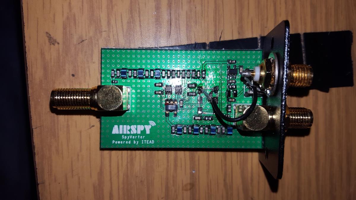
The Airspy already contains an external clock input for 10 MHz, however the present version of the Spyverter contains no such external input. To get around this Tim carefully removed the oscillator on the Spyverter and then added a second SMA connector to connect to the GPSDO.
His final setup consists of the Leo Bodnar GPSDO outputting a 10 MHz and 120 MHz GPS disciplined clock signal that feeds the Airspy and Spyverter respectively. With this Tim found that he needed no initial offset and zero drift was noticed over two days of testing.
Finally Tim also writes that this Leo Bodnar GPSDO could just as easily be used to create a 28.8 MHz clock signal for an RTL-SDR, or any other SDR or upconverter that needs it.
Over on YouTube user Ejo Schrama has uploaded a short video showing a demonstration of radio frequency interference (RFI) from various Arduino based devices he’s built. The interference comes from the local oscillators within the devices which are common to many electronic devices. He writes in the video description:
RFI simply means that there is a part in the radio spectrum that we wouldn’t like to see, it is usually unintentionally caused by devices around us (computers, televisions, radios, clocks, watches, etc etc) that carry local oscillators which are low power transmitters. Sometimes it is caused by illegal transmissions, so a deliberate action.
The oscillators of devices around us oftentimes feed digital circuits, sine wave become block wave, as a result higher order harmonics of the block wave pollute the spectrum. If your receiver is sensitive enough then you will pick up the RFI at some point.
In this video I’m two meter away from an antenna and I tuned the receiver to 48 MHz which is the 3rd harmonic of the 16 MHz oscillator used by all nearby Arduino experiments. Lets see what the spectrum does by turning on and off some arduino’s. The worst RFI generator was a 16 MHz atmel 328p multiplexing four 7-segment LEDs displaying the value of a IR temperature sensor. But also a nearby clock experiment clearly caused some RFI.
The receiver that I used was an airspy, and I’ve put the decimation factor high enough to get some resolution in the spectrum. The frequency offset between the different arduino’s is clearly visible. This is caused by the fact that cheap quartz oscillators are used, their accuracy is usually around 100 ppm, and this mostly determines a frequency bias.
Nowadays it is very difficult to clean up your local shortwave spectrum. For this reason reception conditions under 30 MHz and even 2 meter nowadays face the RFI problem. Only when we go to UHF frequencies like 430 MHz, better known as the the 70 cm amateur band, the RFI problem sort of disappears, apparently because higher harmonics have become insignificant.
I do not think that a lot of effort is put into keeping LW, HF but also VHF spectra clean, the worst violators are usually tracked down but only when many listeners start to complain.
Bob W9RAN recently wrote in to let us know about some developments he and Youssef have had with getting the Airspy to function at full speed on a Raspberry Pi 2 with ADS-B decoding. Bob and Youssef created the SpyVerter upconverter, and Youssef is the programmer of SDR# and the co-creator of the Airspy SDR. Bob writes the following:
Airspy is a high-performance SDR that streams 12 bit samples at 20 MSPS (real, not IQ) to a PC where the real processing is done. But 20 million samples per second uses a significant fraction of the bandwidth available with USB 2.0, and has made apparent the weaknesses in USB subsytems on a number of PCs. So of course the natural assumption by “experts” has been that the Raspberry Pi 2 isn’t up to the task.
As we Pi fans know, the Pi 2 has a 900 Mhz 4-core ARM Cortex A7 CPU, and the key to performance is properly implemented code that can take full advantage of the processor architecture.
Youssef Touil, author of SDR# and creator of Airspy has done that, proving first that an optimized multithreaded version of his ADSB decoder would run on a 4-core Odroid that has more CPU power than the Pi 2. But today we have proven that not only can the Raspberry Pi 2 run the optimized ADSB decoder at full speed (20 million samples per second via USB), but that it even has enough horsepower left to run the Virtual Radar Server Google map display in the Pi’s Epiphany web browser!
For those not familiar, the map display is created by a program called Virtual Radar Server that runs on a PC and receives samples from the Pi over ethernet, and includes a web server that allows other computers (in my case, the Pi 2) to view the composite map display. (For more information about ADSB, see my article in QST for January 2014).
I’m really thrilled to be able to demonstrate that the Pi 2 has this impressive capability! This makes it feasible to create inexpensive high performance ADSB receiving systems, and who knows what else?
Now running adsb_spy on Raspberry Pi 2 PLUS the VRS Google map in the Epihany browser. Sweet! pic.twitter.com/ol5izJmGKK