Category: RTL-SDR

PagerMon: A browser based app for displaying pager messages from multimon-ng

Thank you to Dave for submitting information about his new pager message display software called PagerMon. PagerMon is a web browser based tool for displaying POCSAG pager messages decoded by multimon-ng. It is based around nodejs and uses a sqlite database for storing the messages. Multimon-ng is an RTL-SDR compatible digital mode decoder which can decode multiple protocols including POCSAG pagers.

PagerMon and the features and future features are listed below:

PagerMon is an API driven client/server framework for parsing and displaying pager messages from multimon-ng.

It is built around POCSAG messages, but should easily support other message types as required.

The UI is built around a Node/Express/Angular/Bootstrap stack, while the client scripts are Node scripts that receive piped input.

Features

  • Capcode aliasing with colors and FontAwesome icons
  • API driven extensible architecture
  • Single user, multiple API keys
  • SQLite database backing
  • Configurable via UI
  • Pagination and searching
  • Filtering by capcode or agency
  • Duplicate message filtering
  • Keyword highlighting
  • WebSockets support – messages are delivered to clients in near realtime
  • Pretty HTML5
  • May or may not contain cute puppies

Planned Features

  • Multi-user support
  • Other database support (MongoDB and DynamoDB planned)
  • Horizontal scaling
  • Enhanced message filtering
  • Bootstrap 4 + Angular 2 support
  • Enhanced alias control
  • Graphing
  • Push notifications
  • Non-sucky documentation

The GitHub readme has a getting started section which shows how to set up the server and get it running on your local machine.

PagerMon displaying POCSAG messages

AmateurRadio.com and NooElec.com RTL-SDR Giveaway Competition

Over on AmateurRadio.com there is currently a giveaway where you can win some NooElec SDR packages. Up to 30 prizes are available, and the deadline for entering is 14 June 2017, 18:00 UTC. To enter all you need to do is leave a comment on their post (do not accidentally leave a competition entry comment on this post!). The winner will be announced on their website on 15 June 2017.

The first prize is a NESDR SMArt XTR HF Bundle. The NESDR SMArt XTR is an E4000 unit with SMA connector in the SMArt form factor. E4000 dongles have a higher maximum frequency range of up to 2.3 GHz, but a lower frequency minimum of 64 MHz. However, generally the R820T2 chip has better RF performance. The prize bundle comes with a ham-it-up upconverter, a balun 1:9, and some whip antennas.

The second prize is a NESDR Nano 2+ ADS-B bundle. The Nano 2+ is a small 1 cm x 1 cm dongle which is often used for Android mobile devices, or computing hardware like Raspberry Pi’s. The bundle comes with 1090 and 978 MHz whip antennas and some adapters.

Third prize is the same as the second prize, but with a Nano 2. The difference between the Nano 2 and Nano 2+ is that the Nano 2 does not have a TCXO. The fourth, fifth and sixth prizes are individual dongles.

First and Second Prize in the Giveaway.
First and Second Prize Bundles in the Giveaway.

The Outernet Dreamcatcher: A Linux Based ARM PC with Built in RTL-SDR

Recently Outernet released their new ‘Dreamcatcher’ hardware which is an RTL-SDR + L-band LNA & filter + computing board all on the same PCB. The Dreamcatcher costs $99 USD and can be bought directly from their store. For your $99 you get the Dreamcatcher board, as well as a new ceramic L-band patch antenna which has a built in L-band LNA and filter. The built in LNA is useful as it allows you to use a few meters of extension cable in order to get the patch antenna in a good position outdoors.

At the moment the Dreamcatcher can be run with two different SD card images: the Skylark Outernet software, or Armbian (Linux). The Armbian image is basically just standard Armbian and at the moment does not actually run any Outernet software, and cannot decode their signal – but this is being worked on. Eventually they hope to depreciate the Skylark image and instead use an Outernet receiver app that runs on Armbian.

When running on the standard Armbian image, the Dreamcatcher can be used as a regular RTL-SDR connected to Linux, as there is a bypass port which bypasses the built in L-band LNA and filter. This port is enabled by default, but can be software switched to the L-band port if desired. There is also a 4.8V bias tee on the bypass port that can be turned on in software and used to power external devices via the coax cable. Currently there is no display support on the Dreamcatcher so the unit must be run headless, meaning that you must connect to it via UART or SSH from another PC.

The Outernet Dreamcatcher

The Dreamcatcher is advertised with the following specifications:

  • L-band SAW filter (1525 – 1559 MHz)
  • Two-stage L-band LNA with 34dB gain
  • 1 PPM TCXO
  • RF bypass for tuning from 24 – 1600 MHz – use as a regular RTL SDR!
  • Software switchable bias tee
  • 3 USB ports
  • GPIO forest
  • UARTs, I2C, SPI headers (unpopulated) for driving external hardware
  • Two microSD card holders – for boot and storage!
  • 1 GHz CPU
  • 512 MB RAM
  • USB wifi dongle (based on RTL8188CUS chipset) – AP mode capable!
  • Lots of LEDs!
  • Switches!
  • microUSB OTG
  • microUSB power port
  • Audio In/Out
  • Fully mainline (4.10) kernel and Uboot (2017.01) support!

Also as explained on the forums, Dreamcatcher uses an Allwinner A13 SoC, which has inside an ARM Cortex A8 @ 1 GHz CPU. They’ve also added 512MB of RAM. The PCB measures 12 cm x 12 cm.

Currently the Dreamcatcher is being advertised as beta hardware, as they give the following warning:

Although some assistance can be found on our forums, Outernet provides no direct support for this product. If you are not a tinkerer, hobbyist, or hardware hacker, you may be disappointed with your purchase.

The Dreamcatcher also comes with Outernet’s latest L-band patch antenna. The new patch antenna uses a ceramic patch and a 12 cm x 12 cm PCB ground plane. The antenna is ‘active’, as it has a built in L-band LNA and filtering. It is powered by the bias tee on the Dreamcatcher, and can also be powered by the bias tee on our V3 RTL-SDR’s. An active antenna is a good idea as this allows you to place the antenna outdoors (you’d need to waterproof this antenna in a plastic box though), and run a coax cable inside. The LNA should help overcome the coax cable loss which can be quite high at the L-band Outernet frequency of 1.5 GHz.

Outernet has provided us with a sample of this kit, and we plan to release a full review of the unit within the next few weeks.

Outernet active ceramic patch antenna (Front)
Outernet active ceramic patch antenna (Rear)

Tracking Trains: Monitoring Railroad ATCS Control Signals with an RTL-SDR

Over on his YouTube channel GusGorman402 has uploaded a tutorial which shows how he monitors ATCS (Advanced Train Control System) signals from trains. ATCS signals are found in the USA, and is used for things like communications between trains, rail configuration data, train location data, speed enforcement, fuel monitoring, train diagnostics and general instructions and messages.

In the video he first shows how to determine the frequency of trains signals in your area by using the US FCC database. He then shows how to download and install the ATCSMonitor software which is used for decoding the signals, and then walks us through configuring the correct settings within the software. The train signal audio is piped from SDR# to ATCSMonitor via VBCable, and received with an RTL-SDR and simple whip antenna.

Later in the video he shows how to fully set up the software with train databases so that the actual spotted train names show up. He also shows how to set up the dispatcher display which visually shows the current train locations and track configurations.

GusGorman402 has uploaded the tutorial in two videos. The first shows the full tutorial, configuration and demo for trains in the BNSF fleet. The second video shows how to monitor the Union Pacific fleet which uses a different protocol, which requires a slightly different set up in ATCSMonitor.

RTL-SDR Railroad ATCS Monitor BNSF Omaha

RTL-SDR Railroad ATCS Monitor Union Pacific Omaha

Building a Ground Plane / Spider ADS-B Antenna for 2€

Thanks to Manuel aka Tysonpower for submitting to us his extremely cheap ADS-B antenna build. Manuels ADS-B antenna consists of a simple SMA connector with flange and some wires cut to the correct resonant length for 1090 MHz ADS-B. This ground plane design has been around for years on the internet with atouk’s guide being the most commonly used, although atouk’s design uses a larger SO-239 connector instead. Manuel takes the design one step cheaper by using cheap single core copper wire for the elements, and a low cost SMA connector. The wires are soldered onto the SMA connector flange so you will need to know how to solder to complete the antenna.

Manuel has uploaded a video which shows the build steps for his cheap antenna in a step by step guide. We note that the video is narrated in German, but there are English subtitles.

[EN subs] ADSB Antenne für 2€ - DIY

Does the RTL-SDR.com FM Bandstop Filter Withstand TX Power?

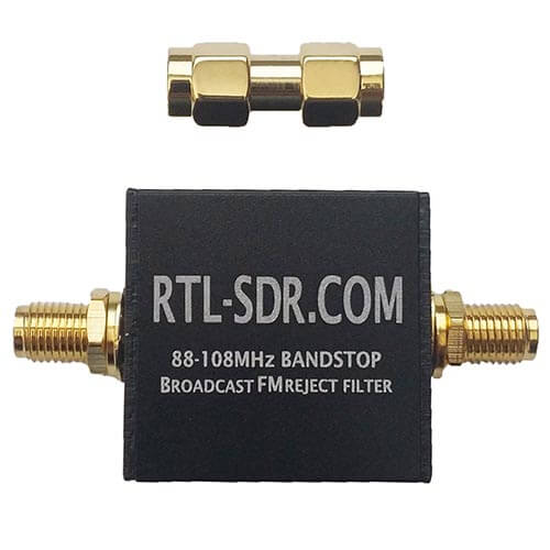
Thanks to PY2RAF for writing in and sharing some tests that he did on our RTL-SDR Blog BCFM bandstop filter. The RTL-SDR Blog filters were designed for RX purposes only, and no provisions were made for TX with only small SMD components being used. However PY2RAF wanted to test to see if the filter could at least handle 5W. The gist of his results is that the filter seems to handle 5W just fine, but as a precaution we wouldn’t recommend that anyone do this unless you really know what you are doing! 

As he does not have a blog, we present PY2RAF’s write up here:


Introduction

I am a Ham Radio Operator (PY2RAF), live in a metropolitan and very RF-polluted area.

Recently, I bought a handheld device and was back to the ether, after a 12-year hiatus. I assembled myself a 3-band quarter-wave “cat whisker” antenna for 144, 220 and 430 MHz (https://rf01.co/q/antena.jpg), calibrated it using a VNA and was quickly back up in the air.

Despite great and complimentary reports of good audio and transmission reports, my reception was sub-par: Lots of interference (QRM), static, squelch closing despite high S-bar signal.

I got intrigued by that, it just did not make sense: Had the VX-8 large mouth but bad ears? After a couple of days puzzled, I got a good idea: Put my RTL-SDR.com filter in the antenna.

The result was great: It immediately reduced the idle band noise from 6-7 S-bars to 3-4 S-bars. The squelched interrupted audio also stopped happening.

So, I could conclude that the strong FM BC band was overloading the receiving stage of the radio. Culprit found.

However, it brought another problem: the filter is NOT designed to cope with TX power (it is actually expressly stated at the product description page). However, the enhancement was just too good and I reached Carl asking about TX support or tests. Carl explained me that while the filter was not designed with TX power in mind, it withstand some minor current, because it supports Bias Tee currents.

I took it as a ‘good enough, I’ll test it’. See the results below.

Material

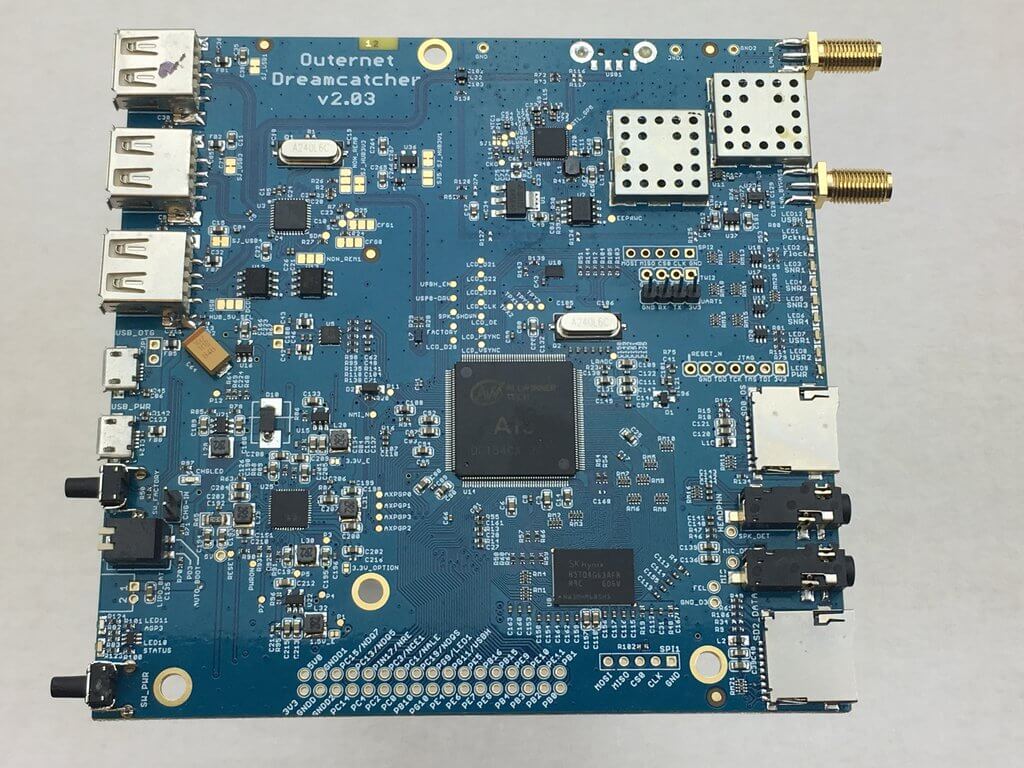
The Device Under Test (DUT) is a RTL-SDR.com FM Bandstop Filter. The transceiver is a Yaesu VX-8DR. I used a PocketVNA Vector Network Analyzer for checking the filter S21 characteristics and antenna S11 VSWR and impedance figures.  The realtime VSWR and TX power were monitored by a Diamond SX-200. I also used a Rtl-SDR.com SDR dongle and GQRX software to check for any transmission distortion. The radiant system (antenna) is a homebrew 3-band multiple dipole antenna, with VSWR < 1:1.3 in frequencies under test.

Method

Prior to any transmission, I put the DUT in the VNA and noted its frequency and attenuation figures.

Next step, assembled the test environment:

Transceiver – wattmeter – DUT – antenna.

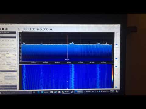
I did then the first test: set the radio to its lowest power (0.05 W) and transmitted in frequency 144.320 MHz. I have also tuned the SDR dongle in the same frequency and watched the  waterfall pattern, while listening for the resulting audio. Then, repeated the very same test now adding the DUT before the antenna. The waterfall signature and the audio quality was pretty much the same and coherent. Transmitted for approx. 30 seconds using the Filter.

In the next step, I repeated the tests raising the TX power to 1W and 2.5W. I requested feedback from a fellow Ham operator and got report that the audio quality was pretty much the same with and without the filter, with no changes in RX S-units figures. It means, it did not distort the audio nor put significant attenuation into the signal.

The next test was the real world conditions test. I switched to the repeater 146.910 MHz, negative shift (actual TX 146.310, https://goo.gl/maps/45cUY58yot52). This repeater is located circa 100 KM north from my residence. After introducing myself to the repeater and stating the device test, I started transmitting first with a single watt: successfully hit the repeater. After around 7 comms averaging around 2 minutes, I asked for feedback with and without the filter: The reports that I have heard were of no change in the quality or fidelity of the transmission. The SWR was being continuously monitored by the Diamond SX-200, paying attention for any component disruption and sudden SWR raise: The operation was just normal. The filter also did not present any temperature change noticeable by touch.

Finally, I raised the TX power to 5W and requested report. I did a 1’30” TX and got report of normal transmission.

Results

This test validated, to me, the useful and robustness of the bandstop filter in my antenna as a permanent solution: It did not change the SWR figure, produced heating, noticeable attenuation or signal distortion: It became, since then, a permanent item between my radio and the antenna.

After the tests, I ran another round of DUT tests in VNA and the attenuation of the filter were the same as original: Working the way it should be.

Next day, I joined the repeater net again and spent around two hours ragchewing in the radio, accumulating something around 25 minutes of TX. Nothing wrong was noticed.

A Final Note

It is important to register that the DUT is working in a nicely matched (VSWR < 1:1.5) antenna system. Unmatched or higher VSWR figures can result in higher voltage, enough to break down the isolation. High-Q antenna systems might also present the same issue.

A Tour of Satellites in the QB50 Experiment

Over the last two weeks the QB50 experiment was launched from the International Space Station (ISS). The experiment consists of 36 cubesats built by various universities around the world, with the main science goal being to make measurements of the thermosphere (an upper atmospheric layer that the ISS orbits in). All the cubesats broadcast their telemetry in the 70cm (420 – 450 MHz) amateur band and they are expected to stay in orbit for about 3 months before falling back to earth. In a previous post we made a point to mention Lilacsat-1, which is one of the most interesting QB50 satellites due to its implementation of a FM to digital voice repeater on board.

The QB50 Experiment Launch

Over on his blog destevez has been following these satellites, and has uploaded a post that shows him receiving and decoding several of the satellite telemetry packets. His gr-satellites GNU Radio package provides a means to decode many of the satellites in the experiment.

Some packets from QB50 and other satellites in the 70cm amateur band.
Some packets from QB50 and other satellites received by destevez in the 70cm amateur band.

YouTube Video: A Tutorial on Receiving and Decoding NOAA and METEOR Satellites

Back in March we posted about The Thought Emporium’s YouTube video that explained weather satellites and demonstrated that images could be downloaded from them using an SDR like a HackRF or RTL-SDR. Now The Thought Emporium have uploaded part two of the video series, which is a tutorial that shows exactly how to use the free software to receive, demodulate and decode NOAA and Meteor satellites.

The first part of the video shows how to use SDR#, Audacity and WXtoIMG to receive NOAA APT weather images. The second part of the video shows how to use SDR#, Audacity, LRPTrx, LRPTofflinedecoder, SmoothMeteor and LRPT processor to receive Meteor M2 LRPT images.

Receiving Images From Satellites Part 2: Decoding and Demodulating NOAA and METEOR Transmissions