—–Hz: A New STD-C Inmarsat Decoder
UPDATE: Unfortunately we have been informed that the code base of this software was illegally decompiled and reused in an almost unchanged way from an already available closed source decoder. This means the program itself is illegal and totally unethical.
Please respect the original developers hard work and do not download this software.
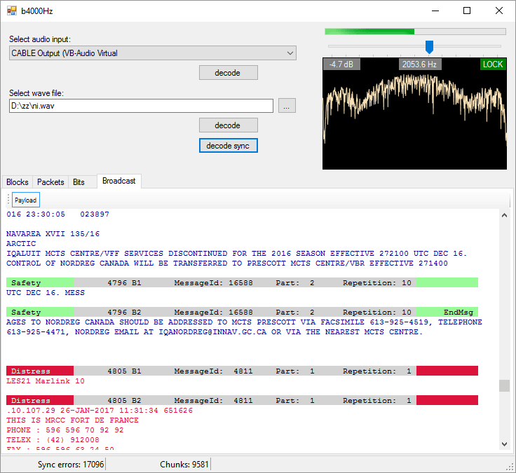
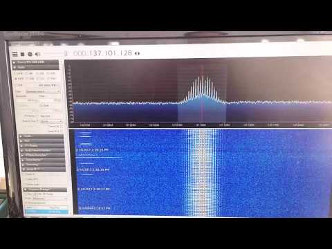
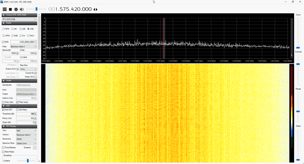
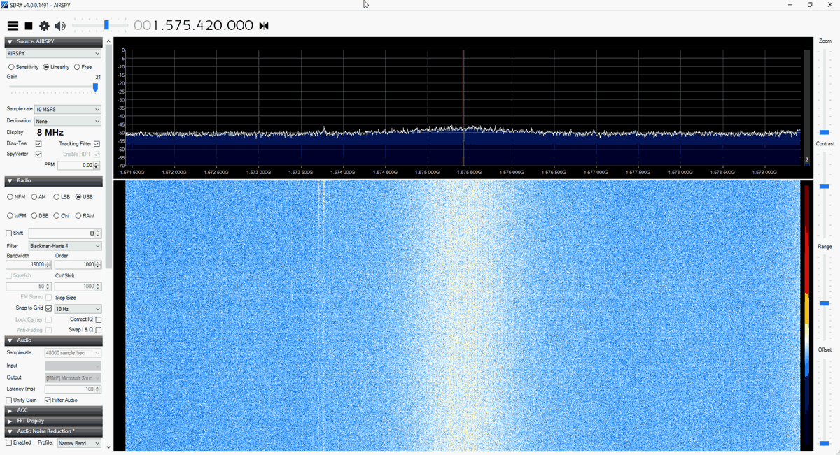
A new STD-C Inmarsat decoder called —-Hz has recently been released. The decoder is Windows based and simply listens to the demodulated Inmarsat STD-C audio from a program such as SDR#. This means that it is compatible with the RTL-SDR, and any other SDR that can receive Inmarsat.
We gave the software a brief test and it ran very well, and managed to decode several SafeteNET messages without issue, maintaining a good lock most of the time. The author writes that he plans to improve on the software in the future by creating a web service based version of the software.
Currently there are two other Inmarsat decoders available. One is called InmarsatDecoder and the other is the Tekmanoid decoder. The InmarsatDecoder is generally regarded as the best, but the Tekmanoid decoder was recently updated for improved performance. The new software appears to be about the same as the Tekmanoid decoder.
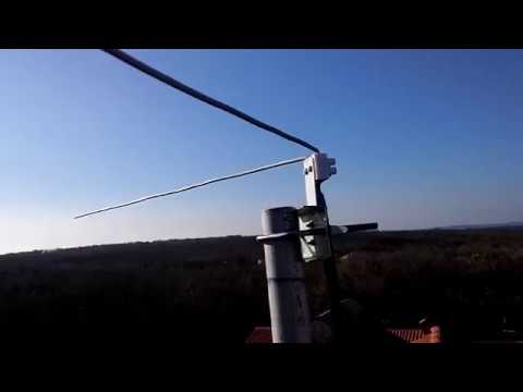
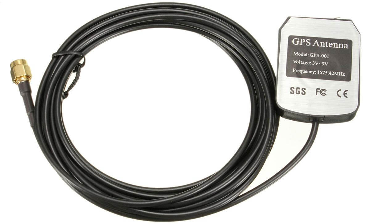
Inmarsat STD-C messages are broadcast from geostationary satellites in the L-band at around 1.5 Ghz. They send mostly marine based messages such as the following quoted from the ——Hz website:
- Safety: high seas, tropical storm warnings, ice accretion…
- Shipping activity: moving oil rigs, submarine cable deployment and repairs…
- Distress reports: MOB, ships lost at sea, migrant ship reports…
- Military exercises (firing practice, no fly zones…)
- Pirate at sea reports…
If you are interested in learning how to decode STD-C we also have a tutorial available here.