The International Space Station periodically schedules radio events where they transmit Slow Scan Television (SSTV) images down to earth for listeners to receive and collect. This time they have scheduled SSTV images for Dec 8 1235 – 1800 UTC, and December 9 1240-1740 UTC. The ARRL announcement reads:
Slow-scan television (SSTV) transmissions from the International Space Station (ISS) are scheduled for December 8-9. The SSTV images will be transmitted from RS0ISS on 145.800 MHz FM as part of the Moscow Aviation Institute MAI-75 Experiment, using the Kenwood TM-D710 transceiver in the ISS Service Module.
MAI-75 activities have been scheduled on December 8, 1235-1800 UTC, and December 9, 1240-1740 UTC. These times correspond to passes over Moscow, Russia. ISS transmissions on 145.800 MHz FM use 5-kHz deviation, and SSTV transmissions have used the PD120 and PD180 formats.
The ISS Fan Club website can show when the space station is within range of your station. On Windows PCs the free application MMSSTV can decode the signal. On Apple iOS devices, use the SSTV app.
These SSTV broadcasts can usually be easily heard with an RTL-SDR and appropriate satellite antenna such as a QFH, Turnstile or a hand held Yagi. Many listeners have reported in the past as being able to receive them even with non-satellite antennas such as discones, ground plane, rubber duck and long wire antennas, so try your luck even if you don’t have the right antenna.
We recommend using the Orbitron software to track the ISS, but you can also use the web tracker on issfanclub.com as recommended by the ARRL.
An SSTV image from the ISS sent last April from http://www.issfanclub.com/node/40913
A radio repeater is usually a radio tower that receives weak signals from handheld, desktop or other radio, and rebroadcasts the same signal at a higher power over a wide area at a different frequency. This allows communications to be extended over a much greater area.
Repeaters are generally made from expensive professional grade radio equipment, however ZR6AIC has been experimenting with creating an ultra low cost repeater out of a RTL-SDR and Raspberry Pi. In his system the RTL-SDR dongle is set up to receive a signal on the 70 cm (420 – 450 MHz) amateur radio band, and then retransmit it using Rpitx on the 2M (144 – 148 MHz) amateur radio band. He also adds a 2M low pass filter to the output of the Raspberry Pi to keep the signal clean.
RTL-SDR + Rpitx Block Diagram
Rpitx is software for the Raspberry Pi which we have featured on this blog several times in the past. We’ve also seen the qtcsdr software which also uses Rpitx and an RTL-SDR to create a transceiver. Rpitx allows the Raspberry Pi to transmit radio signals without the need for any transmitting radio hardware at all. It works by modulating signals onto a General Purpose I/O (GPIO) pin on the Raspberry Pi. If the GPIO pin is modulated in just the right way, FM/AM/SSB or other signal modulation approximations can be created at a specified frequency. The signal is however not clean, as this type of modulation generates many harmonics which could be dangerous if amplified. If you use Rpitx, always use appropriate filtering hardware.
ZR6AIC’s post goes into detail about how to install and set up the required software onto the Raspberry Pi and how to set up the script to piece all the programs together into a repeater. He’s also uploaded a video demonstrating the system in action on YouTube.
Back in September 2015 we made a post about how Bastian Bloessl was able to use his RTL-SDR dongle to reverse engineer and decode the signals coming from portable wirelessly synchronized traffic lights which are commonly set up around road construction zones.
To reverse engineer these new lights he made a recording of the signals in GQRX and then opened them up in Inspectrum, which is a very nice tool for helping to reverse engineer digital signals. Thanks to Inspectrum he was easily able to extract the preamble and decode the data in GNU Radio.
Bastian has also uploaded a video that shows him reverse engineering the binary frame format in the Vim text editor which may be useful for those wishing to understand how it’s done.
Reversing Frame Format with Vim
Once the frame format was reverse engineered, he was able to use the program he created last year which allows him to view the status of the lights remotely in real time.
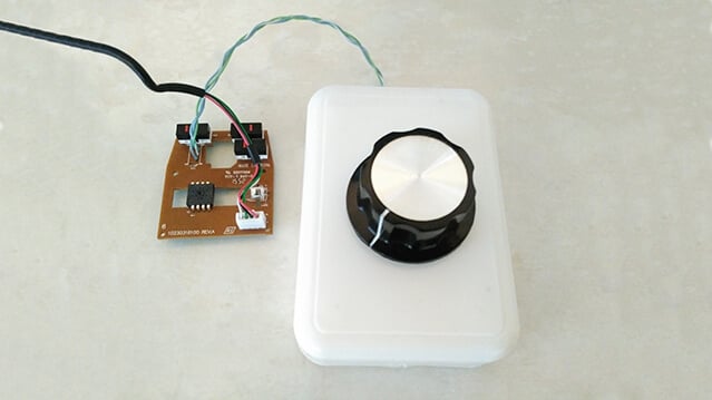
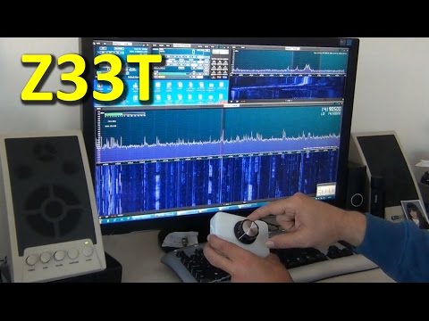
Over on YouTube user Mile Kokotov has uploaded a new video showing his SDR frequency controller in action. The controller allows you to tune the frequency with a knob, which is preferred over the keyboard and mouse by many. In his video he shows it in action on the SDRUno software.
The controller is made out of a simple rotary encoder and a USB mouse. The rotary encoder is an EC16 (with no detents/clicks). It is connected up to the mouse PCB instead of the scroll wheel. Mile mentions that the encoder only cost him about $2 from eBay, and the mouse only $3, bringing the total cost of the project to only $5. More information and images can be found on his project page.
The rotary encoder connected to the USB mouse PCB.
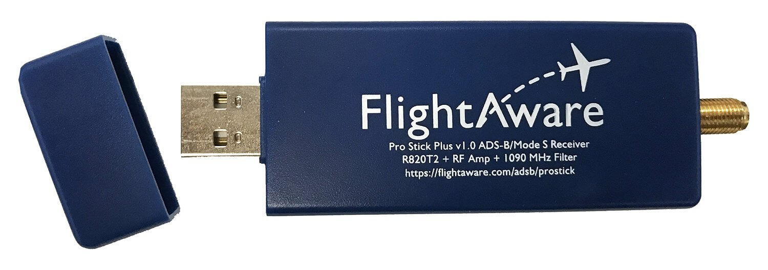
Recently the FlightAware Prostick Plus was released. The Prostick is a modified RTL-SDR with a LNA built into the dongle. It is optimized for ADS-B reception and works very well due to the low noise figure of the SKY7150 LNA which is used as the first stage LNA. However, due to the increased gain from the LNA it can easily overload from strong out of band signals, such as broadcast FM, DAB, DVB-T and GSM. To eliminate this problem FlightAware recommend using their 1090 MHz filter in front of the dongle.
The FlightAware Prostick Plus is the same as the Prostick, but the Plus also incorporates a 1090 MHz SAW filter into the dongle itself. The overall cost is about $15.95 USD cheaper than buying the Prostick + Filter combination. See below for a tabulated comparison between the two units.
Type: LC Passband: 980 – 1150 MHz Insertion Loss: 1.65 dB Attenuation: 40 – 50 dB
Type: SAW Passband: 1,075 MHz – 1,105 MHz Insertion loss: 2.3 dB Attenuation: 30 dB
TCXO
Old batches NO. New batches YES.
YES
Current Draw
330 mA
300 mA
The new Pro Stick Plus RTL-SDR based ADS-B Receiver from FlightAware.
The first thing we notice is that the filter arrangement between the two units is reversed. On the Prostick the filter is external and must be placed before the LNA. This has the advantage of excellent rejection of out of band signals, but increases the noise figure (NF) of the system slightly. A higher noise figure means the ADS-B signal will end up being weaker, resulting in less range and reports. However, the FlightAware 1090 MHz filter has low insertion losses and should only increase the NF by 1-2 dB.
The Prostick Plus on the other hand uses a SAW filter positioned after the LNA. SAW filters at 1090 MHz typically have an insertion loss of anywhere between 2-3 dB’s. But since it is placed after the LNA the losses are almost completely eliminated by the gain from the LNA and thus the total NF remains low. The attenuation of the SAW filter is less, but it has a smaller pass band. The small pass band may be useful for people who live near an airport and suffer issues with interference from the 1030 MHz interrogation pulses or from GSM at 950 MHz.
In theory, the Prostick + Filter should operate better in environments with very strong out of band signals (any signal outside of 1090 MHz). And the Prostick Plus should operate better in environments with weaker out of band signals. The theory is that since the LNA is placed first in the signal chain on the Prostick Plus, it is more susceptible to overloading from the strong signals as it has no protection from a filter. The LNA used in both Prosticks is a SKY7150, which has a very high OIP3 rating. High OIP3 means that its performance in the presence of strong signals is excellent, and it will not overload so easily. However, even a very high OIP3 rated LNA cannot withstand the strong broadcast signals in some locations.
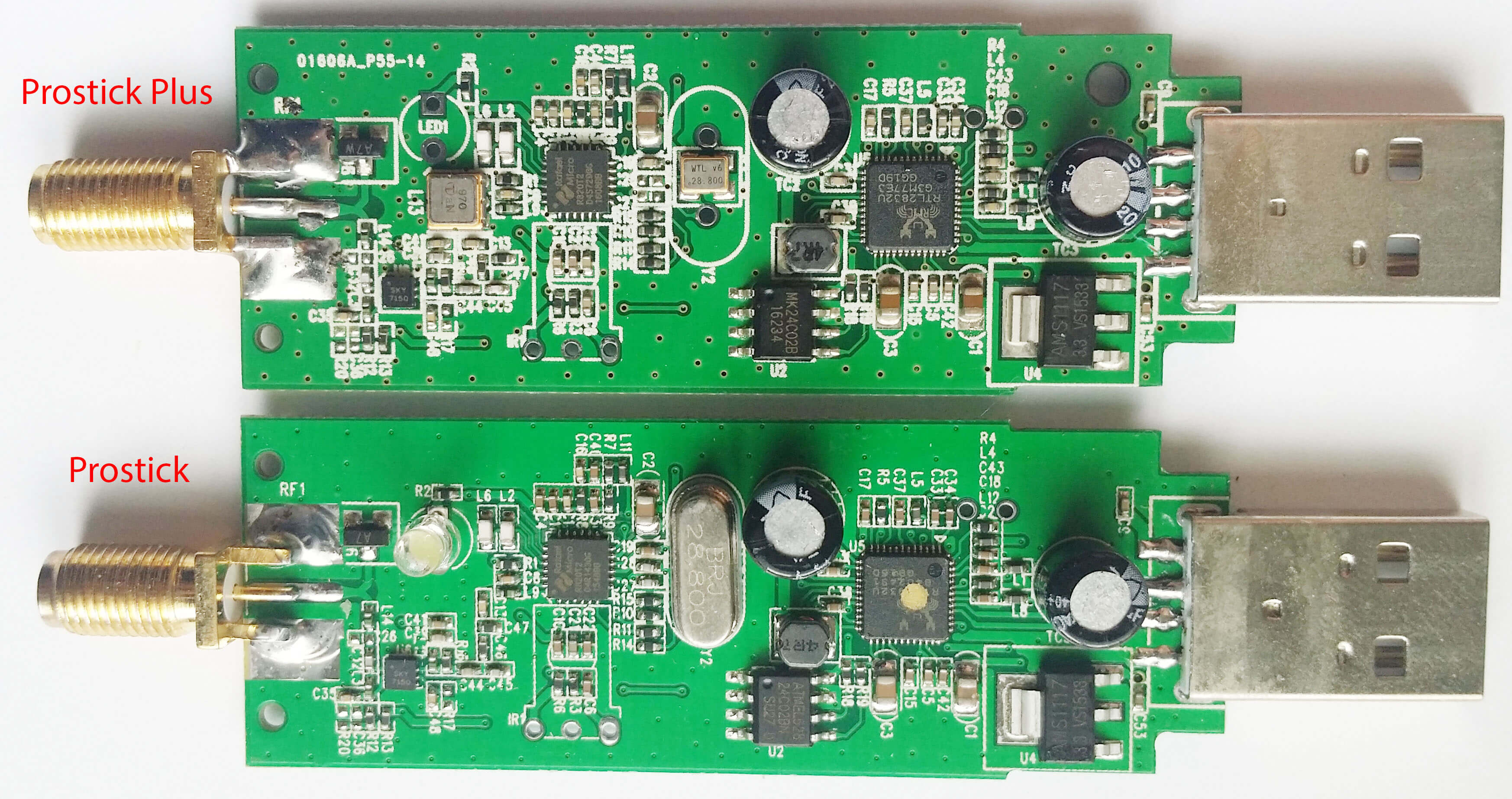
The Prostick Plus also has some other enhancements like a TCXO. ADS-B is very tolerant to frequency drift, so a TCXO won’t really improve decoding performance, but the cost of a 28.8 MHz TCXO purchased in bulk is under $1 USD, so they may have decided to add it anyway. They appear to also be using TCXO’s on the new production batches of the Prostick as well. The Plus also only draws 300 mA of current compared to the Prostick which draws 330mA. This may be due to the removal of the LED (Although the new batches of the Prostick might also have the LED removed as they advertise a power draw of 300 mA.) On the image of the PCBs below you can see the difference. The SAW filter is just underneath where the LED used to be.
Again, as we mentioned in our previous review of the Prostick it is a bit odd that the 39 dB OIP3 SKY7150 only appears to be drawing 60 mA, when it should be drawing 100 mA. The lower current usage is probably because they run it from 3.3V instead of 5V. The lower current use probably means that the OIP3 rating is reduced slightly by ~5 dBs.
The Prostick Plus and Prostick PCBs
Real World Testing
Here we test the Prostick and Prostick Plus in a signal environment with lots of strong interfering BCFM, DVB-T and GSM signals around. We’ve seen reports on the FlightAware forums that some users have seen improved performance with the Prostick Plus, whilst others have seen dismal or reduced performance. In these tests and review we are able to show when each stick will perform at its best. We do not test the Prostick without the filter, as without the filter we are unable to receive any ADS-B messages at all due to overloading.
Test 1: Flight Aware ADS-B Antenna
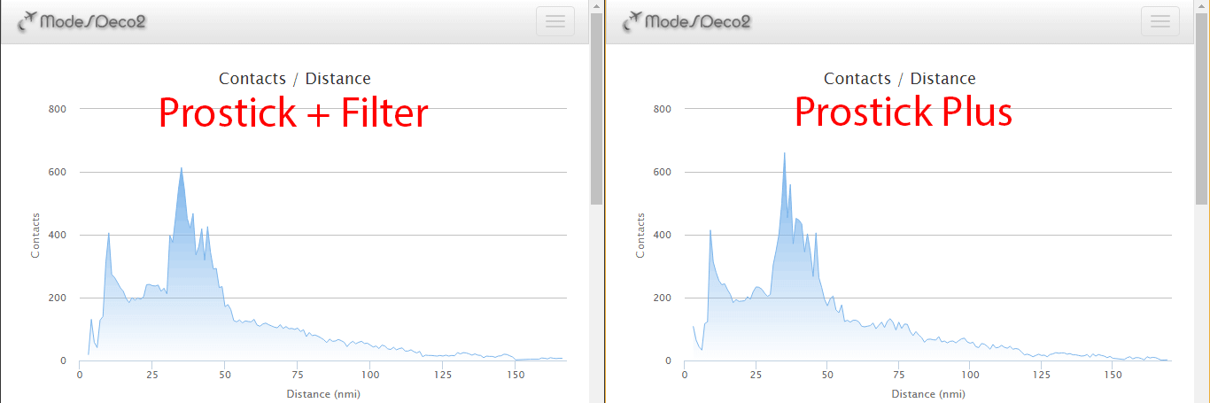
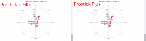
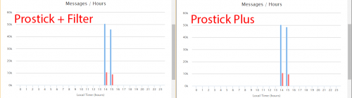
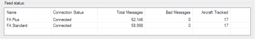
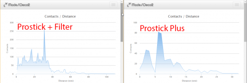
First we set up a test using the FlightAware ADS-B antenna, a 2-way signal splitter and the Prostick Plus and Prostick + Filter. We used Modesdeco2 as the ADS-B software, and ran the test for 45 minutes.
The results show that the Prostick Plus edges ahead of the Prostick + Filter by a small amount. It seems that the 1-2 dB loss in the external filter does not contribute to a huge reduction in ADS-B messaging, but the results do show that the Prostick Plus will give you better results in an environment with favorable reception conditions.
In this test we used the excellent FlightAware ADS-B antenna. This antenna is tuned specifically to 1090 MHz, and performs some rejection of the out of band signals. This rejection is enough to allow the Prostick Plus to work well in our test area without overloading.
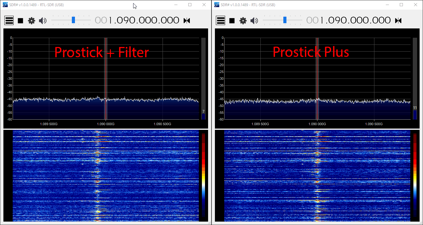
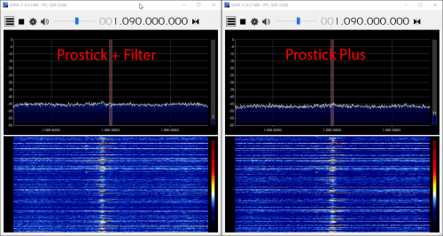
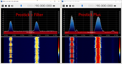
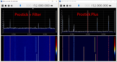
In the image slider below we first checked ADS-B reception in SDR#, to see if there was any noticeable visual difference. The reception seemed identical. In the remaining images we checked to see how the reception was on out of band signals with the two units. In these tests we want the out of band signals to be low, so smaller signals are better. The Prostick Plus filters our out band signals significantly less, which can be a reason for increased overload. But the amount of filtering performed by the Plus was sufficient together with this 1090 MHz tuned antenna to not cause any overload at max gain.
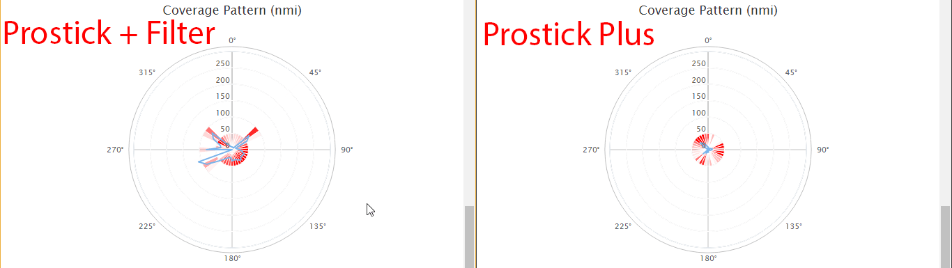
Test 2: Discone Antenna
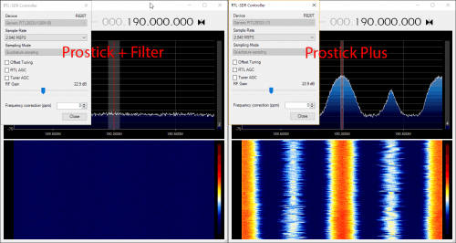
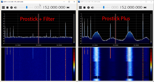
In test 2 we show what can happen if the out of band signals going into the Prosticks are really strong. This could especially happen if you are using a wideband antenna that is not specifically tuned to 1090 MHz, or if the out of band signals in your area are exceptionally strong (living near a transmission tower for example). In this test we used the same setup as in test 1, but used a wideband discone as the antenna instead. This means that the natural out of band signal filtering from the FlightAware antenna is not present anymore, and thus out of band signals come into the dongle much stronger.
Here we found that the Prostick Plus produced dismal results. The out of band signals were too strong for the LNA to handle, thus causing overload and significant desensitization of the ADS-B signals. The messages received by the Prostick + Filter was significantly higher.
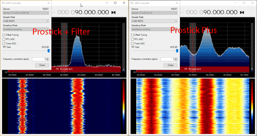
In the SDR# screenshots below we can clearly see that the Prostick Plus has very poor ADS-B reception at 1090 MHz with this antenna. The noise floor is much higher due to desensitization and overload from broadcast FM and DVB-T signals. Reducing the gain on the RTL-SDR does not help a lot, since most of the overload occurs in the first stage SKY7150 LNA. This can also be seen in the amount of signal overload that is present when tuned to the broadcast FM and other bands in SDR#.
Conclusions
The Prostick and Prostick Plus dongles are both excellent low cost ADS-B receivers. If you want to set up a permanent ADS-B monitoring station they are highly recommended.
So what are the lessons learned from these tests?
If you live in an environment with extremely strong out of band signals you’ll need to place the filter first. So in this case use the Prostick + external filter combination (or Prostick Plus + external Filter).
Otherwise use the Prostick Plus for slightly better performance and lower cost.
To reduce the possibility of overload with the Prostick Plus use an antenna tuned to 1090 MHz.
The table below summarizes the recommendations again.
Antenna -> LNA -> Filter (Prostick Plus)
Antenna -> Filter -> LNA (Prostick + FA Filter)
Advantages
Noise figure (NF) is dominated by the LNA, thus this method gives minimum NF.
Losses in filter overcome by LNA gain.
LNA will not be susceptible to overloading from out of band signals.
Disadvantages
The LNA can overload from out of band signals since it is not protected by a filter.
The insertion loss (IL) of the filter directly adds to the noise figure (NF). For example a 2 dB IL filter will add 2 dB to the system NF. This may result in a few dB’s lower SNR.
When to use
Use this method if you do not have strong out of band signals in your area and/or if you have an LNA with a high OIP3 rating, like with the SKY7150 LNA which is used on the Prostick’s.
Use this method if you have very strong out of band signals in your area.
For most people the Prostick Plus should work fine and be the better choice. Also rest assured that if you purchase a Prostick Plus and find that it overloads in your environment, you still always have the option of placing an external filter in front of it. Then you’ll practically have the same performance as with the standard Prostick + Filter combination. A Prostick Plus + External Filter combination may even be more beneficial for users in very very strong signal environments.
Also remember that the Prostick’s are designed to be placed as close to the antenna as possible, without the use of coax cable. You can use USB extension cables, or run the Prostick on a remote Raspberry Pi computing unit to achieve this. If you want to run coax between the antenna and Prostick, you will see heavily reduced performance due to the losses in the coax cable. In this situation you should instead place an LNA like the LNA4ALL or Uputronics ADS-B LNA by the antenna, and use a bias tee to power it.
The International Space Station periodically schedules radio events where they transmit Slow Scan Television (SSTV) images down to earth for listeners to receive and collect. This time they have scheduled SSTV images for Dec 8 1235 – 1800 UTC, and December 9 1240-1740 UTC. The ARRL announcement reads:
Slow-scan television (SSTV) transmissions from the International Space Station (ISS) are scheduled for December 8-9. The SSTV images will be transmitted from RS0ISS on 145.800 MHz FM as part of the Moscow Aviation Institute MAI-75 Experiment, using the Kenwood TM-D710 transceiver in the ISS Service Module.
MAI-75 activities have been scheduled on December 8, 1235-1800 UTC, and December 9, 1240-1740 UTC. These times correspond to passes over Moscow, Russia. ISS transmissions on 145.800 MHz FM use 5-kHz deviation, and SSTV transmissions have used the PD120 and PD180 formats.
The ISS Fan Club website can show when the space station is within range of your station. On Windows PCs the free application MMSSTV can decode the signal. On Apple iOS devices, use the SSTV app.
These SSTV broadcasts can usually be easily heard with an RTL-SDR and appropriate satellite antenna such as a QFH, Turnstile or a hand held Yagi. Many listeners have reported in the past as being able to receive them even with non-satellite antennas such as discones, ground plane, rubber duck and long wire antennas, so try your luck even if you don’t have the right antenna.
We recommend using the Orbitron software to track the ISS, but you can also use the web tracker on issfanclub.com as recommended by the ARRL.
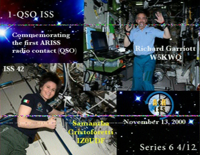
An SSTV image from the ISS sent last April from http://www.issfanclub.com/node/40913
A radio repeater is usually a radio tower that receives weak signals from handheld, desktop or other radio, and rebroadcasts the same signal at a higher power over a wide area at a different frequency. This allows communications to be extended over a much greater area.
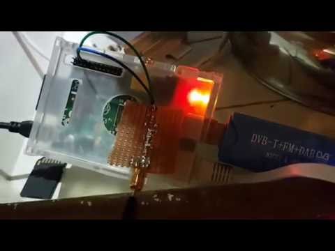
Repeaters are generally made from expensive professional grade radio equipment, however ZR6AIC has been experimenting with creating an ultra low cost repeater out of a RTL-SDR and Raspberry Pi. In his system the RTL-SDR dongle is set up to receive a signal on the 70 cm (420 – 450 MHz) amateur radio band, and then retransmit it using Rpitx on the 2M (144 – 148 MHz) amateur radio band. He also adds a 2M low pass filter to the output of the Raspberry Pi to keep the signal clean.
RTL-SDR + Rpitx Block Diagram
Rpitx is software for the Raspberry Pi which we have featured on this blog several times in the past. We’ve also seen the qtcsdr software which also uses Rpitx and an RTL-SDR to create a transceiver. Rpitx allows the Raspberry Pi to transmit radio signals without the need for any transmitting radio hardware at all. It works by modulating signals onto a General Purpose I/O (GPIO) pin on the Raspberry Pi. If the GPIO pin is modulated in just the right way, FM/AM/SSB or other signal modulation approximations can be created at a specified frequency. The signal is however not clean, as this type of modulation generates many harmonics which could be dangerous if amplified. If you use Rpitx, always use appropriate filtering hardware.
ZR6AIC’s post goes into detail about how to install and set up the required software onto the Raspberry Pi and how to set up the script to piece all the programs together into a repeater. He’s also uploaded a video demonstrating the system in action on YouTube.
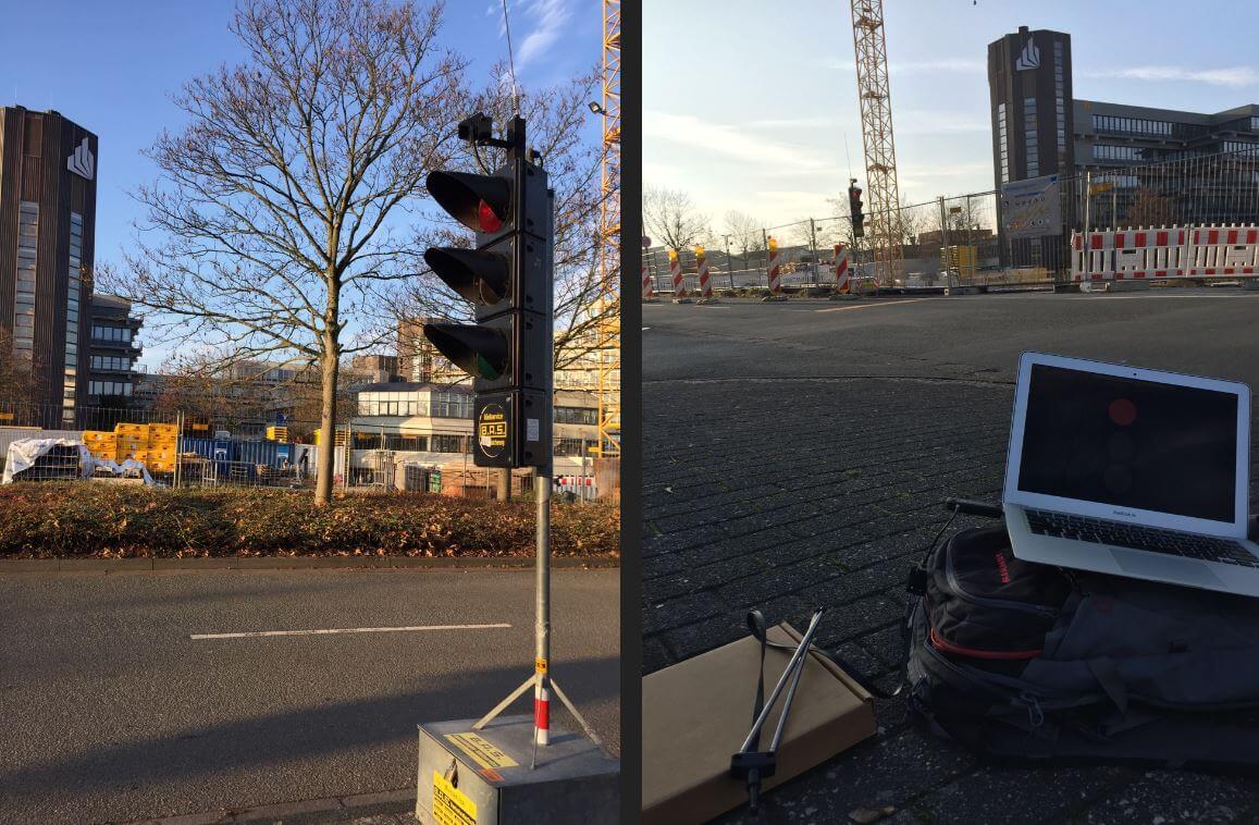
Back in September 2015 we made a post about how Bastian Bloessl was able to use his RTL-SDR dongle to reverse engineer and decode the signals coming from portable wirelessly synchronized traffic lights which are commonly set up around road construction zones.
To reverse engineer these new lights he made a recording of the signals in GQRX and then opened them up in Inspectrum, which is a very nice tool for helping to reverse engineer digital signals. Thanks to Inspectrum he was easily able to extract the preamble and decode the data in GNU Radio.
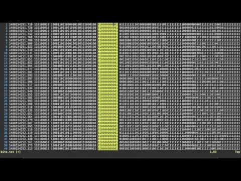
Bastian has also uploaded a video that shows him reverse engineering the binary frame format in the Vim text editor which may be useful for those wishing to understand how it’s done.
Reversing Frame Format with Vim
Once the frame format was reverse engineered, he was able to use the program he created last year which allows him to view the status of the lights remotely in real time.
Over on YouTube user Mile Kokotov has uploaded a new video showing his SDR frequency controller in action. The controller allows you to tune the frequency with a knob, which is preferred over the keyboard and mouse by many. In his video he shows it in action on the SDRUno software.
The controller is made out of a simple rotary encoder and a USB mouse. The rotary encoder is an EC16 (with no detents/clicks). It is connected up to the mouse PCB instead of the scroll wheel. Mile mentions that the encoder only cost him about $2 from eBay, and the mouse only $3, bringing the total cost of the project to only $5. More information and images can be found on his project page.
The rotary encoder connected to the USB mouse PCB.
Recently the FlightAware Prostick Plus was released. The Prostick is a modified RTL-SDR with a LNA built into the dongle. It is optimized for ADS-B reception and works very well due to the low noise figure of the SKY7150 LNA which is used as the first stage LNA. However, due to the increased gain from the LNA it can easily overload from strong out of band signals, such as broadcast FM, DAB, DVB-T and GSM. To eliminate this problem FlightAware recommend using their 1090 MHz filter in front of the dongle.
The FlightAware Prostick Plus is the same as the Prostick, but the Plus also incorporates a 1090 MHz SAW filter into the dongle itself. The overall cost is about $15.95 USD cheaper than buying the Prostick + Filter combination. See below for a tabulated comparison between the two units.
Type: LC Passband: 980 – 1150 MHz Insertion Loss: 1.65 dB Attenuation: 40 – 50 dB
Type: SAW Passband: 1,075 MHz – 1,105 MHz Insertion loss: 2.3 dB Attenuation: 30 dB
TCXO
Old batches NO. New batches YES.
YES
Current Draw
330 mA
300 mA
The new Pro Stick Plus RTL-SDR based ADS-B Receiver from FlightAware.
The first thing we notice is that the filter arrangement between the two units is reversed. On the Prostick the filter is external and must be placed before the LNA. This has the advantage of excellent rejection of out of band signals, but increases the noise figure (NF) of the system slightly. A higher noise figure means the ADS-B signal will end up being weaker, resulting in less range and reports. However, the FlightAware 1090 MHz filter has low insertion losses and should only increase the NF by 1-2 dB.
The Prostick Plus on the other hand uses a SAW filter positioned after the LNA. SAW filters at 1090 MHz typically have an insertion loss of anywhere between 2-3 dB’s. But since it is placed after the LNA the losses are almost completely eliminated by the gain from the LNA and thus the total NF remains low. The attenuation of the SAW filter is less, but it has a smaller pass band. The small pass band may be useful for people who live near an airport and suffer issues with interference from the 1030 MHz interrogation pulses or from GSM at 950 MHz.
In theory, the Prostick + Filter should operate better in environments with very strong out of band signals (any signal outside of 1090 MHz). And the Prostick Plus should operate better in environments with weaker out of band signals. The theory is that since the LNA is placed first in the signal chain on the Prostick Plus, it is more susceptible to overloading from the strong signals as it has no protection from a filter. The LNA used in both Prosticks is a SKY7150, which has a very high OIP3 rating. High OIP3 means that its performance in the presence of strong signals is excellent, and it will not overload so easily. However, even a very high OIP3 rated LNA cannot withstand the strong broadcast signals in some locations.
The Prostick Plus also has some other enhancements like a TCXO. ADS-B is very tolerant to frequency drift, so a TCXO won’t really improve decoding performance, but the cost of a 28.8 MHz TCXO purchased in bulk is under $1 USD, so they may have decided to add it anyway. They appear to also be using TCXO’s on the new production batches of the Prostick as well. The Plus also only draws 300 mA of current compared to the Prostick which draws 330mA. This may be due to the removal of the LED (Although the new batches of the Prostick might also have the LED removed as they advertise a power draw of 300 mA.) On the image of the PCBs below you can see the difference. The SAW filter is just underneath where the LED used to be.
Again, as we mentioned in our previous review of the Prostick it is a bit odd that the 39 dB OIP3 SKY7150 only appears to be drawing 60 mA, when it should be drawing 100 mA. The lower current usage is probably because they run it from 3.3V instead of 5V. The lower current use probably means that the OIP3 rating is reduced slightly by ~5 dBs.
The Prostick Plus and Prostick PCBs
Real World Testing
Here we test the Prostick and Prostick Plus in a signal environment with lots of strong interfering BCFM, DVB-T and GSM signals around. We’ve seen reports on the FlightAware forums that some users have seen improved performance with the Prostick Plus, whilst others have seen dismal or reduced performance. In these tests and review we are able to show when each stick will perform at its best. We do not test the Prostick without the filter, as without the filter we are unable to receive any ADS-B messages at all due to overloading.
Test 1: Flight Aware ADS-B Antenna
First we set up a test using the FlightAware ADS-B antenna, a 2-way signal splitter and the Prostick Plus and Prostick + Filter. We used Modesdeco2 as the ADS-B software, and ran the test for 45 minutes.
The results show that the Prostick Plus edges ahead of the Prostick + Filter by a small amount. It seems that the 1-2 dB loss in the external filter does not contribute to a huge reduction in ADS-B messaging, but the results do show that the Prostick Plus will give you better results in an environment with favorable reception conditions.
In this test we used the excellent FlightAware ADS-B antenna. This antenna is tuned specifically to 1090 MHz, and performs some rejection of the out of band signals. This rejection is enough to allow the Prostick Plus to work well in our test area without overloading.
In the image slider below we first checked ADS-B reception in SDR#, to see if there was any noticeable visual difference. The reception seemed identical. In the remaining images we checked to see how the reception was on out of band signals with the two units. In these tests we want the out of band signals to be low, so smaller signals are better. The Prostick Plus filters our out band signals significantly less, which can be a reason for increased overload. But the amount of filtering performed by the Plus was sufficient together with this 1090 MHz tuned antenna to not cause any overload at max gain.
Test 2: Discone Antenna
In test 2 we show what can happen if the out of band signals going into the Prosticks are really strong. This could especially happen if you are using a wideband antenna that is not specifically tuned to 1090 MHz, or if the out of band signals in your area are exceptionally strong (living near a transmission tower for example). In this test we used the same setup as in test 1, but used a wideband discone as the antenna instead. This means that the natural out of band signal filtering from the FlightAware antenna is not present anymore, and thus out of band signals come into the dongle much stronger.
Here we found that the Prostick Plus produced dismal results. The out of band signals were too strong for the LNA to handle, thus causing overload and significant desensitization of the ADS-B signals. The messages received by the Prostick + Filter was significantly higher.
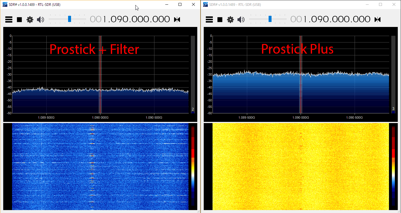
In the SDR# screenshots below we can clearly see that the Prostick Plus has very poor ADS-B reception at 1090 MHz with this antenna. The noise floor is much higher due to desensitization and overload from broadcast FM and DVB-T signals. Reducing the gain on the RTL-SDR does not help a lot, since most of the overload occurs in the first stage SKY7150 LNA. This can also be seen in the amount of signal overload that is present when tuned to the broadcast FM and other bands in SDR#.
Conclusions
The Prostick and Prostick Plus dongles are both excellent low cost ADS-B receivers. If you want to set up a permanent ADS-B monitoring station they are highly recommended.
So what are the lessons learned from these tests?
If you live in an environment with extremely strong out of band signals you’ll need to place the filter first. So in this case use the Prostick + external filter combination (or Prostick Plus + external Filter).
Otherwise use the Prostick Plus for slightly better performance and lower cost.
To reduce the possibility of overload with the Prostick Plus use an antenna tuned to 1090 MHz.
The table below summarizes the recommendations again.
Antenna -> LNA -> Filter (Prostick Plus)
Antenna -> Filter -> LNA (Prostick + FA Filter)
Advantages
Noise figure (NF) is dominated by the LNA, thus this method gives minimum NF.
Losses in filter overcome by LNA gain.
LNA will not be susceptible to overloading from out of band signals.
Disadvantages
The LNA can overload from out of band signals since it is not protected by a filter.
The insertion loss (IL) of the filter directly adds to the noise figure (NF). For example a 2 dB IL filter will add 2 dB to the system NF. This may result in a few dB’s lower SNR.
When to use
Use this method if you do not have strong out of band signals in your area and/or if you have an LNA with a high OIP3 rating, like with the SKY7150 LNA which is used on the Prostick’s.
Use this method if you have very strong out of band signals in your area.
For most people the Prostick Plus should work fine and be the better choice. Also rest assured that if you purchase a Prostick Plus and find that it overloads in your environment, you still always have the option of placing an external filter in front of it. Then you’ll practically have the same performance as with the standard Prostick + Filter combination. A Prostick Plus + External Filter combination may even be more beneficial for users in very very strong signal environments.
Also remember that the Prostick’s are designed to be placed as close to the antenna as possible, without the use of coax cable. You can use USB extension cables, or run the Prostick on a remote Raspberry Pi computing unit to achieve this. If you want to run coax between the antenna and Prostick, you will see heavily reduced performance due to the losses in the coax cable. In this situation you should instead place an LNA like the LNA4ALL or Uputronics ADS-B LNA by the antenna, and use a bias tee to power it.
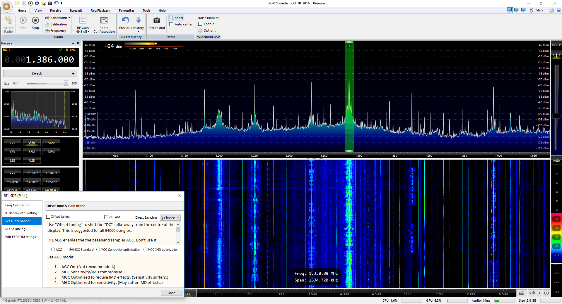
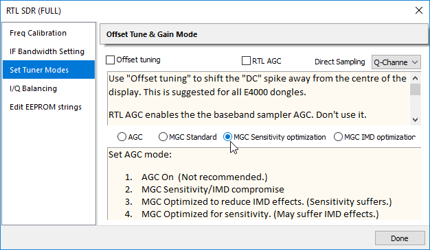
For SDR-Console users jdow’s ExtIO and driver now has an option to enable the direct sampling mode, which is allows the HF mode on our V3 dongles to be activated. The ExtIO module can be downloaded from her Google drive.
To use Joannes drivers download the SDRconsole folder by right clicking it, and selecting download. Then copy files from the x86 (32-bit) or x64 (64 bit) folders into the SDRConsole folder, replacing any files that already exist. Run the RtlSdr Catalog.exe file, then open SDR-Console and from the definitions choose RTL-SDR(Full). Then in the Radio Configuration settings you can choose to use the Q-branch, which will automatically enable the direct sampling mode when tuned below 24 MHz.
SDRConsole with a V3 dongle and HF Direct Sampling.
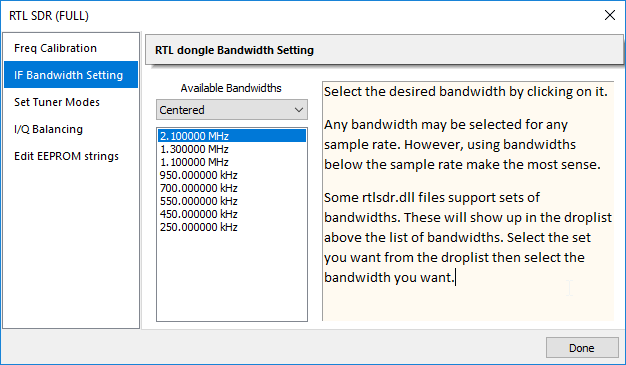
We’ve also discovered that Joanne has been working on RTLSDR++, which is a driver upgrade that includes some pretty interesting enhancements. When running Joanne’s drivers in SDR-Console we also see options to change the IF filter bandwidths of the R820T2 tuner. This is very useful as this allows you to control the preselector on board the R820T2. You can use this to attenuate strong out of band signals. Her driver also has improved gain profiles. One gain profile is optimized to reduce IMD distortion (prevent overload and images), and the other is designed to optimize sensitivity.
RTLSDR++ Driver: New IF bandwidth settings for preselection.RTLSDR++ Drivers: New Gain Options
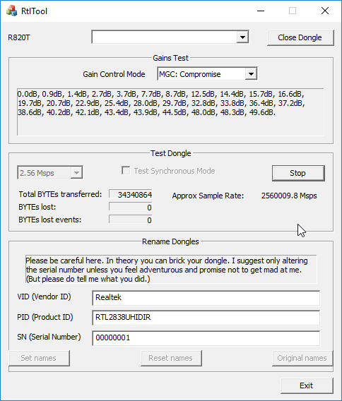
In addition Joanne has also created RtlTool.exe which is a GUI replacement for rtl_test.exe and rtl_eeprom.exe. It can be used to test for lost samples on your RTL-SDR and to flash the EEPROM memory. Most RTL-SDR dongles on most PCs are stable up till 2.56 MSPS, but this tool can be used to check. It can also be used to set the dongle serial number, vendor ID and name by flashing the EEPROM which most RTL-SDRs contain.
There’s also the RtlSdr Catalog tool which also helps manage multiple dongles being connected to the PC at once. See the readme file for more information on using this tool.
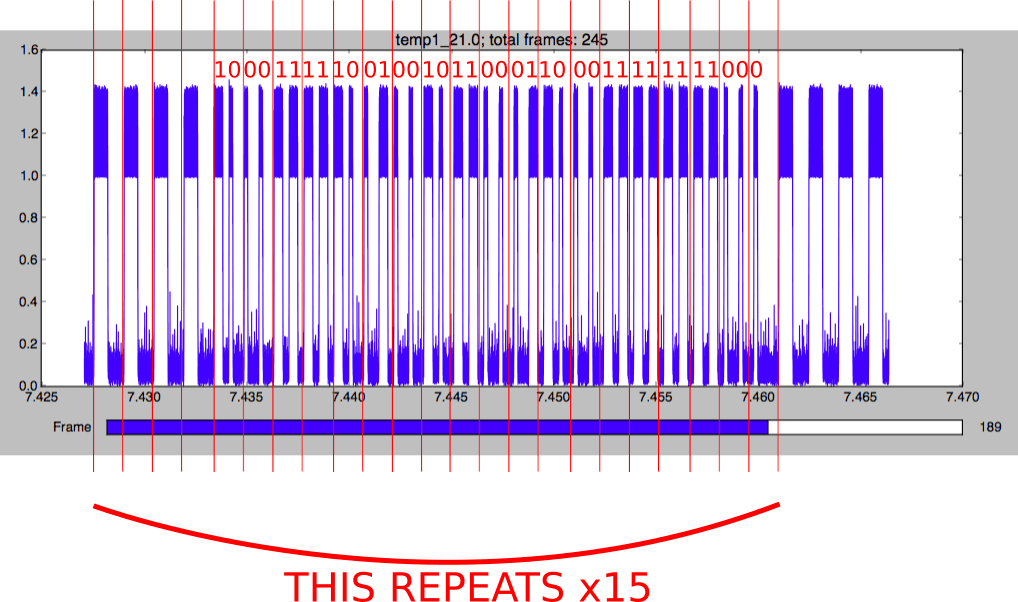
First he explains how he used Python to extract the data from the RTL-SDR I/Q samples. From those samples he calculates the amplitude data, and plots it on a graph which shows the digital signal. He then decimates the signal to reduce the number of samples and figures out how to detect the preamble, data bits and packet repetitions. Then to decode the signal he explains how he does clock recovery, convolution and thresholding, and also the importance and meaning of those steps.
If you’re new to reverse engineering signals and don’t have a DSP background, then spenmcgee’s write up is an excellent starting point. It’s written in a way that even a layman should be able to understand with a little effort. If you have a Lacross TX29 wireless temperature meter that you just want to decode, then his code will also be of use.
NOTE: Please do not go to the Nongles.com site linked in this post as it has been taken over by explicit content. This post is from 2016 and is outdated as ThumbNet have moved away from dongle hardware. This post is now only kept up for archival purposes.
A few days ago we received a production sample of the new ThumbNet N3 receiver. Our sample came with the works, which includes the green aluminum enclosure and shielding can soldered on over the PCB. This full set costs $33.50 USD + $4.50 USD international shipping, but there are cheaper options if you do not want the aluminum case or the RFI shield.
We've only had a brief time to play around with it so far, but it's performance seems very similar to the prototype unit that they sent us earlier. We intend to give the N3 a longer review next week but our first impressions are favorable. In this post we'll simply unbox the unit, show some photos and give it a quick turn on test.
The N3 comes in a protective cardboard box with the N3 and Thumbnet/Nongles logo on it. Inside sits the ThumbNet N3 unit itself, and there is a power plug terminal block adapter located on the bottom of the box. Excluding the F-type connector, the ThumbNet unit has dimensions of 6.2 cm x 4 cm x 2.1 cm, and weighs 58g. The green enclosure is strong and rugged.
Unlike the prototype they sent, this unit can run direct from USB power alone. We saw that it draws about 400 mA of power, and we had no trouble running it from our 1A capable USB ports. Of course one of the main advantages to the N3 is the ability to power it with a low noise external power supply, and we will be testing that in the next review.
Nongles SDR Lego
ThumbNet have also announced their new sister site, Nongles.com. On this site they intend to soon begin selling something called "Nongles" which is a mashup of "NOt a dONGLE". Nongles are an idea that can be best described as a type of "SDR Lego", and we think will be very interesting to people interested in experimenting with different SDR set ups and for use in education. Nongles will be based on the RTL-SDR design, but they are going to be split the RTL-SDR up into several discrete PCB modules/blocks such as:
R820T2 Module
RTL2832U Module
Experimenter Module
External Clock Module
LNA
Bias Tee
Signal Amplifier
50 - 75 Ohm Transformer
Filter blocks such as SAW/FM Bandstop/High Pass/Low Pass and other DIY kits
Obviously you'll at least need the R820T2 and RTL2832U blocks to have a working system. Then the other blocks can then be added in as needed. The Nongles are not ready for sale yet so keep an eye on their website for news of their release.