Category: RTL-SDR

Our Quick Review of the ThumbNet N3 Prototype

Earlier this month Akos from the RTLSDR4Everyone blog reviewed a prototype of the latest ThumbNet N3 RTL-SDR. In this post we will also give a quick review of a prototype of their new unit which was kindly provided to us by ThumbNet. ThumbNet is a company that is hoping to provide low cost satellite deployments, and make use of volunteers around the world with RTL-SDR’s to help track them. The RTL-SDR’s and antenna kits are provided to schools and educational institutions for free by ThumbNet, in exchange for students setting up and monitoring a satellite tracking station.

To help with the needs of their project they have designed and manufactured the ThumbNet N3, which is a redesigned RTL-SDR dongle. As they must order in bulk, they are also selling surplus units to the RTL-SDR community with the hope that any profits will help fundraise for other related projects.

The ThumbNet N3 is a redesigned RTL-SDR with a focus on lowering the noise floor and spurs for optimal reception of their satellites. The N3 uses a 0.5 PPM TCXO for low frequency drift and a common mode USB choke for reduced USB noise. The PCB size is also increased allowing for better thermal dissipation. Since F-type is more common in the areas they intend to donate the units to, an F-type antenna connector is used on the dongle. A full list of the changes and improvements they’ve made can be found on their N3 details page.

One way in which they have reduced the noise is by disabling the internal switching voltage regulator within the dongle, and instead using a linear regulator. Linear regulators are much quieter than their switching counterparts, however they do draw significantly more power. The N3 draws 450mA of current, wheras a standard RTL-SDR draws closer to 270mA. Since many USB ports have a 500 mA limit this gets close to problematic to run directly from the USB port. To get around this, the N3 has an external power port, so it can be powered by an AC->DC power pack (like what you use for charging your phone), or more ideally with a quieter linear power supply or batteries. This has the added advantage of avoiding noisy USB power lines.

Review & Testing

The N3 feels very sturdy, and all the connectors are mounted strongly and are unlikely to break off. The top of the receiver shows the power port, the USB port, the shielding can and the F-type connector. The USB connector uses the older depreciated “USB mini” standard (which is different to USB micro found on most phones).

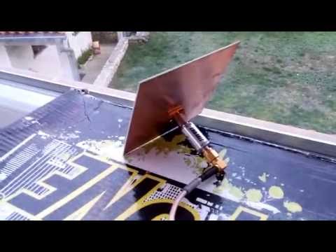
The bottom shows a few components as well as the two linear regulators. In order to power the unit we used an AC to DC 5V power supply (normally used for mobile phone charging) which we soldered on to the bottom of the PCB. Ideally we’d use a battery or linear power supply, but we’ll test that later with the actual production unit.

The standard N3 unit comes with no enclosure or RFI shielding cans (these are paid add-ons). Our prototype unit came with a shielding can covering the components which was enough to block most interfering signals. We did not see many unwanted signals being received with the antenna unplugged which is a good sign that the shielding can is doing its job.

Thumbnet N3 Top
Thumbnet N3 Top
Thumbnet N3 Bottom
Thumbnet N3 Bottom

We gave the unit a quick test on a noise floor scan. The results show that the noise floor has been significantly reduced. The clock spurs are still there but they are reduced in strength vs the standard RTL-SDR.

A standard RTL-SDR vs RTL-SDR Blog V3 vs ThumbNet N3 noise floor scan

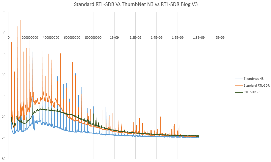
On L-band at around 1.5 GHz the standard RTL-SDR dongles tend to fail at receiving after they heat up a little. The ThumbNet N3 showed no problems in this region, probably thanks to its larger PCB with better heat dissipation.

Conclusion

Once the production model is released we intend to do a more in depth review, but as it stands right now the N3 is looking very good especially for those who use RTL-SDR’s in monitoring applications that can benefit from very low noise floors, or for those who like the idea of being able to externally power the unit.

The ThumbNet N3 can be bought from their store. It costs $25.75 (with no shielding can), $27.75 (with shielding can), $31.50 (with aluminum case and no shielding can) or $33.50 (with aluminum case and shielding can) + $4.50 worldwide shipping. ThumbNet write that initial demand for the N3 unit has been high, so if you are interested in the unit, you need to order early to ensure that you can get one. They are due to ship out by the end of October. We’ve received a note that the delivery date is rescheduled for no later than November 11. 

Also in a recent email from ThumbNet they wrote:

First of all, let me thank you from the whole team, for your support of ThumbNet and helping to promote STEM education around the globe with your purchase. We have sold more of the surplus N3’s than we expected to at this point, so if you have friends that are hesitant, tell them that time is running out! 🙂

Secondly, I wanted to take a moment to update you on the status.

The production run testing of the N3 was completed on time, but testing found three small improvements we could put into effect immediately, to produce a better receiver. Those changes have been submitted to the manufacturer and we are currently waiting for a revised ship date.

We still anticipate that the N3 will ship in the month of October, but I will send a follow up email with a more accurate schedule, when I get one in a day or two, from the manufacturer.

I thank you all for your understanding and patience. All of our testing so far indicates that the N3 is performing very well, and we hope you’ll agree it was worth the wait, when it arrives.

Reverse Engineering the Outernet Signal

Outernet is a satellite based file delivery service. Currently they’re beta testing their service and they are using RTL-SDR’s as the receiver. In previous posts we’ve seen that they’re now regularly transmitting weather updates, wikipedia files and more files like images and books. Over time the service is becoming more and more useful. If you’re interested in receiving their service we have a tutorial available here.

While most of the Outernet software is open sourced, the signal protocol itself is closed source, which ties you into needing to use the official Outernet software. Over on his blog, Daniel Estévez has been working on reverse engineering the Outernet signal with the goal of publishing the results and building a fully open source receiver.

So far he’s managed to fully reverse engineer the modulation, coding and framing. He’s also been able to build a GNU Radio program that receives the Outernet frames and a Python program called free-outernet which does the decoding. His post goes into greater details on how he reverse engineered the signal and what his finding are.

The Outernet Concept

A Multi-Channel Coherent RTL-SDR Product: For Passive Radar, Direction Finding and More

Coherent-receiver.com is a company which is a customer of our RTL-SDR V3 dongle and they have been working on creating a multi-channel coherent receiver product based on the RTL-SDR. An RTL-SDR multi-channel coherent receiver is at its most basic, two or more RTL-SDR dongles (multi-channel) that are running from a single clock source (coherent). A multi-channel coherent receiver allows signal samples from two different antennas to be synchronized against time, allowing for all sorts of interesting applications such as passive radar and direction finding.

The team at coherent-receiver.com have used the new expansion headers on our V3 dongles to create their product. In their receivers they attach a control board which has a buffered 0.1 PPM TCXO (buffered so it can power multiple RTL-SDR’s). They also added an 8-bit register and I2C connection capabilities which allows for control of future add-on boards. The I2C capability is useful because it means that several RTL-SDR dongles can be controlled and tuned from the same control signal. More information on the registers and build of the receiver control board can be seen on their technical support page.

A ten channel RTL-SDR coherent receiver.
The Coherent Receiver block diagram.

One example application of a multi-channel coherent receiver is passive radar. Coincidentally, we’ve just seen the release of new GUI based Passive Radar software by Dr. Daniel Michał Kamiński in yesterdays post. Passive radar works by listening for strong signals bouncing off airborne objects such as planes and meteors, and performing calculations on the signals being received by two antennas connected to the multi-channel coherent receiver.

A second example is direction finding experiments. By setting up several antennas connected to a multichannel coherent receiver calculations can be made to determine the direction a signal is coming from. An interesting example of direction finding with three coherent RTL-SDRs can be seen in this previous post. A third example application is pulsar detection which we have seen in this previous post

Coherent-receiver.com sent us a prototype unit that they made with four of our V3 dongles. In testing we found that the unit is solidly built and works perfectly. We tested it together with Dr. Kamiński’s passive radar software and it ran well, however we do not have the correct directional antennas required to actually use it as a passive radar yet. In the future we hope to obtain these antennas and test the coherent receiver and the software further.

Currently they do not have pricing for these models as it seems that they are first trying to gauge interest in the product. If you are interested in purchasing or learning more they suggest sending an email to [email protected]. It seems that they are also working on additional RTL-SDR ecosystem products such as filters, downconverters, antennas and LNAs.

We hope that the release of this product and Dr. Kamiński’s software will give a boost to the development of coherent multi-channel receivers as we have not seen much development in this area until recently.

SDRDue running on the coherent-receiver.com unit.

SDRDue: New Software for Passive Radar with Two Coherent RTL-SDR Dongles

UPDATE March 2019: Daniel's site has gone down, but the downloads are still available here.

Dr. Daniel Michał Kamiński, author of two SDR# plugins has recently released a new passive radar program for the RTL-SDR called "SDRDue". Passive radar is a technique that makes use of signals from strong distant transmitters. The idea is that these signals can be reflected off the fuselage of aircraft or other flying objects, and the reflection can be observed by a passive radar receiver. By correlating data from two receivers and two antennas, more accurate positional data can be obtained.

For passive radar to work properly the receivers should be coherent, meaning that they run from the same clock and have synchronized samples. The RTL-SDR can be made coherent by connecting two dongles to a single clock source.

The software runs on multi-threaded C# code, and uses Microsoft XNA 4.0 for the graphical operations. It also supports GPU parallel calculations if you have OpenCL and an AMD graphics card.

Please note that we attempted to run the program, but it would not even open on our PC. We've contacted the author to ask if there is any known problems. If anyone gets it running please report back in the comments section of this post. EDIT: Daniel has updated the software and it appears to be functioning normally now. You will need to install it into a SDR# folder, and run SDR# first with both dongles before the software will recognise the dongles in SDRDue. We also had better luck with using the rtlsdr.dll_ file, rather than the default rtlsdr.dll file. Just delete the original rtlsdr.dll and rename rtlsdr.dll_ to rtlsdr.dll.

For more information on passive radar we recommend looking at this previous post where we showed the work of Juha Vierinen who used RTL-SDR's to build a passive radar.

The SDRDue Passive Radar Software

Outernet Weather Updates Now Coming Down

A few days ago we reported that the Outernet L-band satellite service had just upgraded their software to make it available for receiving APRS and weather updates. Back then it wasn’t clear what the weather updates would entail. Today weather updates starting being transmitted. They are using NOAA data and displaying it on a live weather app (which can also be viewed online here).

The app can be used to view weather data such as wind vectors, temperatures, relative humidity, total precipitable water, total cloud water, mean sea level pressure and ocean currents. Outernet writes that the global weather data will be updated via their satellite system once per day, and that each update also provides 24h, 48h and 72h predictions. 

We also see that grib files for mariners are now coming in as well as several Wikipedia articles and regular APRS broadcasts from the ISS.

It looks like the Outernet service is becoming more and more useful over time. If you are interested in receiving Outernet with an RTL-SDR see our tutorial post here.

New SDR# Plugin: Radio-Sky Spectrograph Data Stream

Edit: If you downloaded an older version of the plugin please note that it has now been updated. The update fixes some stability issues which would previously hang SDR#. The updated .dll file can be downloaded directly from https://goo.gl/0dPzOL.

Radio-Sky Spectrograph is a radio astronomy software program which is often used together with the RTL-SDR or other similar SDRs. It is best explained by the author:

Radio-Sky Spectrograph displays a waterfall spectrum. It is not so different from other programs that produce these displays except that it saves the spectra at a manageable data rate and provides channel widths that are consistent with many natural radio signal bandwidths. For terrestrial , solar flare, Jupiter decametric, or emission/absorption observations you might want to use RSS.

Usually to interface an RTL-SDR with Radio-Sky Specrtograph a program called RTL-Bridge is used. However, now SDR# plugin programmer Alan Duffy has created a new plugin that allows SDR# to interface with Radio-Sky Spectrograph via a network stream. This allows it to work with any SDR that is supported by SDR# plugins. Alan Duffy writes:

I wrote the plugin after becoming interested in amateur radio astronomy. The plugin allows you to use any of the software defined radios supported by SDR# to feed the Radio-Sky Spectrograph program with wide-band data. The plugin shows the frequency, bandwidth, and FFT resolution and has a user selected "Number of Channels" that are sent to the spectrograph program with an allowable range of 100 to 500. This number can only be edited when the data stream is not enabled. Also if certain key parameters change, such as the frequency or decimation, the network stream will stop as the spectrograph would no longer be capturing the same data. If this happens, simply click the start button on client side software (i.e. Radio-Sky Spectrograph). As long as the Enable box is checked on the server side, the plugin will listen for a connection and start transmitting data after RSS makes a new request for data.

We note that the software might also be useful for simply capturing a long term waterfall for finding active frequencies or looking for meteor scatter or aircraft scatter echoes. 

The Radio-Sky Spectrograph SDR# Plugin

Software for creating an Interactive RTL_POWER Visualization

RTL-SDR.com reader Dominic Chen recently wrote in to let us know about a new piece of software he’s created. The software is called d3-waterfall, and is an interactive web based waterfall display. It takes CSV data from the commonly used rtl_power software and produces an interactive labelled waterfall which can be viewed in a web browser. rtl_power is a program that allows RTL-SDRs to produce signal power scans over an arbitrarily wide swath of bandwidth, by quickly hopping between ~2 MHz chunks of live bandwidth.

Dominics software is built using “d3.js” and HTML5. The waterfall axes are automatically labelled, there are multiple color schemes and there is pan/zoom support. The main feature is that it is mouse interactive, so when you mouse over a frequency it shows what the signal is. The default signal frequency data is taken directly from our sister site sigidwiki.com, so it may not be accurate for your particular area. But the labels are editable, so it can be customized.

An example of a previous scan can be seen on Dominic’s website (note that this is a 65mb link so be careful if you are data restricted). The software can be downloaded from its GitHub page.

The interactive waterfall.

L-Band Setup with Mini LNA4ALL and Mini Patch Antenna

Over on his YouTube channel Adam 9A4QV has uploaded a new video showing reception of L-band signals with a bias tee powered LNA4ALL and a small patch antenna. The video seems to show a new miniature bias tee powered LNA4ALL device that Adam might be working on. The LNA4ALL is a low noise amplifier that works well with our bias tee capable RTL-SDR dongles.

The patch antenna is made out of a single piece of PCB board which was made by etching out the patch pattern with masking tape. While the patch antenna is not optimal, and tested indoors, Adam is still able to receive some AERO signals.

Later in the video he compares the PCB patch against a GPS patch antenna which gets no reception. He also compares the results when two LNA4ALL’s are used in series. Using two LNA’s improves reception slightly.