Recently two students (Léo Poughon and his friend Thomas Daniel) wrote in to let us know about their work with SDR’s for their school project. Their project was to try and repeat the work of “Operation RAFTER” which was a technique use by MI5 in the 60’s to find hidden soviet spy radio equipment. Essentially, all superhet radios (almost any consumer radio is of the superhet design) will emit unintentional emissions from its local oscillator. By tuning to these unintentional emissions, and then emitting your own signal, it is then possible to know what frequency a radio is listening to.
They write the following:
As a french student (sorry for my bad english) in Higher School Preparatory Classes, I (and a friend) had to work with a rtl-sdr dongle for a school project. We tried to do, with the help of amateur radio near Toulouse (F6GUS, his club F5KUG) the same thing as the “RAFTER Operation” (https://en.wikipedia.org/wiki/Operation_RAFTER ) did during the 60′ : hearing at unintentional electromagnetic emissions coming from a widely-used consumer superhet receiver.
So because of its structure, a superheterodyne receiver (i.e. listening at FM broadcast) spreads some unintentional radiations due to the local oscillator upstream the mixer. Anybody with a suitable receiver (for example any rtl-sdr based dongle) can receive these emissions. Because of standards, in most FM radio the local oscillator (that is what the user actually tune) is tuned at the frequency he wants to listen plus 10.7 MHz. So if somebody in the close neighborhood is listening at a broadcast at 100 MHz, you will be able to “receive” its local oscillator at 110.7 MHz. (Please note it may be illegal in some countries to listen at these bands)
What is interesting is to know if a signal you receive at these frequency is actually coming from a radio receiver. During the RAFTER Operation, MI5 broadcast on the band they thought to be heard by soviet spies, and then listened for “the change in the superhet tone” to identify them.
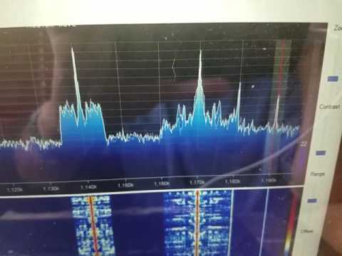
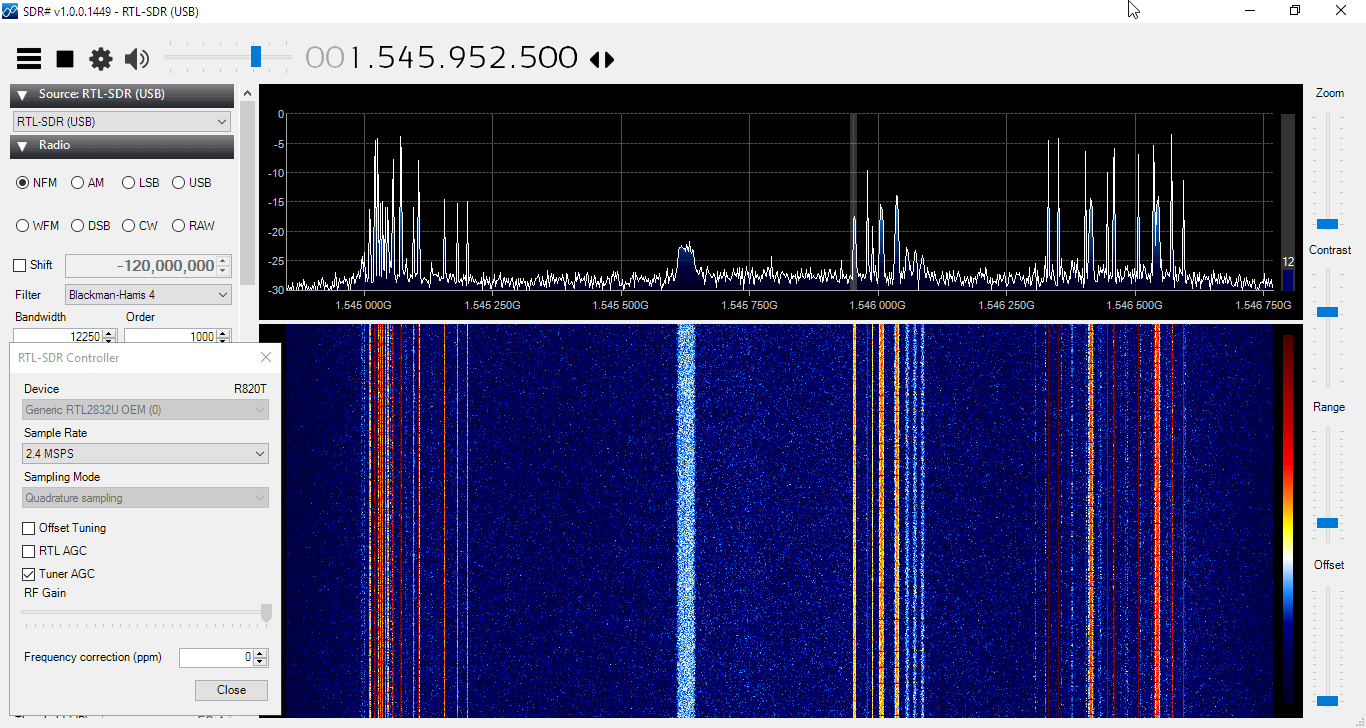
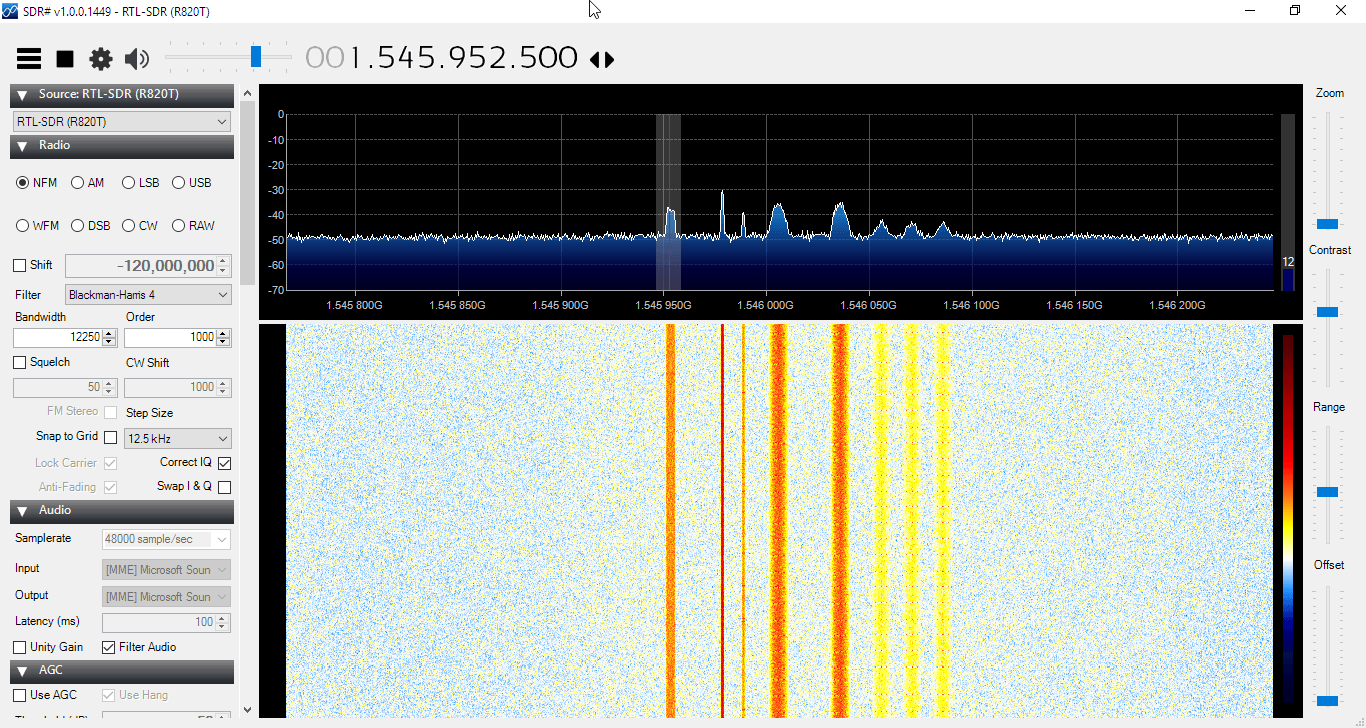
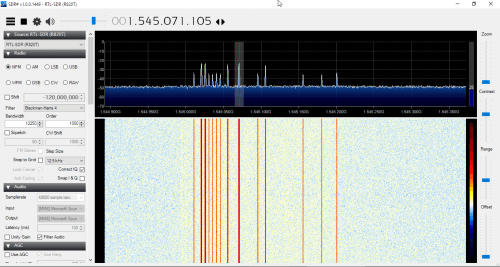
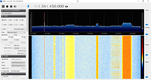
We was able to receive with RTL-SDR the Local Oscillator of a superhet receiver we own.
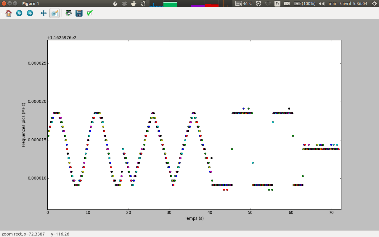
We can see that the frequency isn’t stable on most of the time (the receiver was tuned to “France Info”, a french public station), but becomes stable sometime (when there is a “blank” between two news) : the frequency of the local oscillator “follows” what the superhet receiver demodulates.
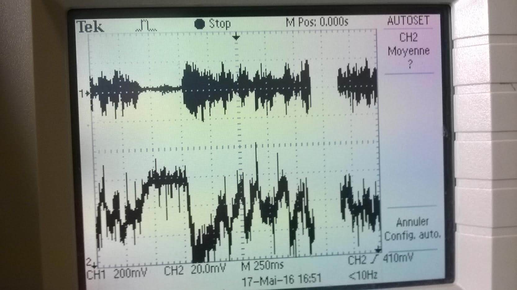
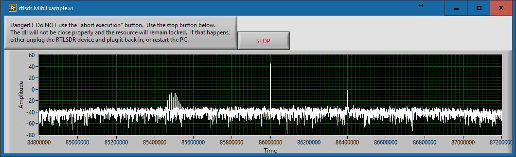
Among other factors, a variation of the supply voltage of the local oscillator can make its frequency slightly shift. So we established experimentally a link between the supply voltage of our radio receiver and what is broadcast via the speaker (because when a speaker is using electrical current, the supply voltage slightly varies).
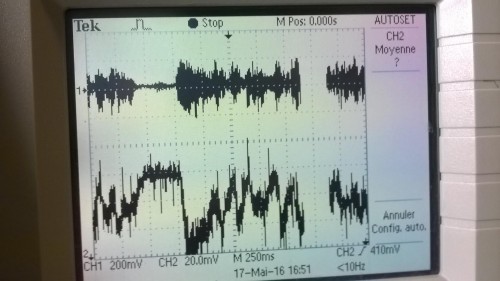
On the top, the HP voltage, and behind there is the supply voltage. Then, we saw that voltage variations could make the frequency to vary
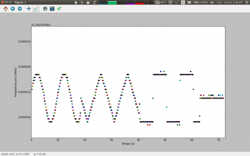
Here we supply the receiver (with a low frequency generator) making the supply voltage slightly varying and plot the frequency of local oscillator with a Python script we made.
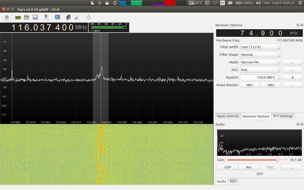
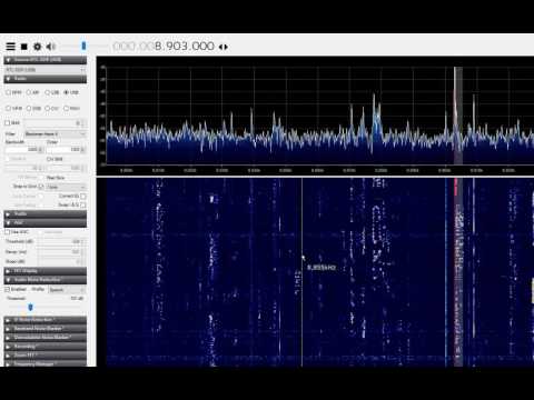
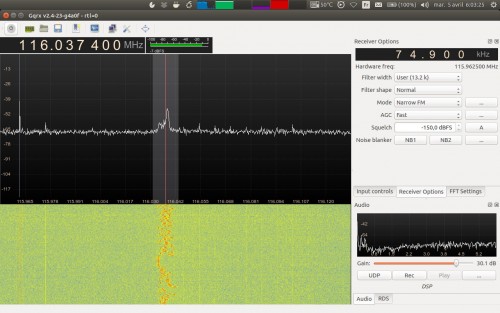
Then, listening at the radio receiver local oscillator with GQRX and our RTL-SDR dongle, demodulating it with “narrow FM” demodulation and adapted parameters, we could hear with the PC (and obviously with poorer quality) what the radio receiver was listening at.
With the stock antenna we could hear at our radio only a dozen meters away, but with a homemade very low quality discone antenna we could receive it on another building, 60 meters away of our antenna. The ability to listen more or less the local oscillator broadcast depends also of the shielding of the radio receiver, its price (because a cheap radio will have a bad power supply and so its local oscillator frequency can “follow” what the speaker is telling, allowing us to “listen” at the local oscillator spike) and how you supply it (with the power grid or with batteries).
To conclude, we could (more or less depending on the previously cited parameters) know what a radio receiver in the neighbourhood was listening to using a RTL-SDR.