Category: RTL-SDR

Using a Beam Deflection Tube as a Mixer for an RTL-SDR Upconverter

Over on YouTube user Full spectrum technician has uploaded an interested video where he shows how he used a beam deflection tube to create an upconverter for his RTL-SDR. A beam deflection tube is a type of vacuum tube that can be used as a mixer. If you aren’t aware, a vacuum tube (a.k.a tube or valve) is an electrical component that was used in electrical equipment heavily back in the first half of the 1900’s. They could be used to implement circuits like amplifiers, mixers, switches, oscillators and more. Even today they are still used in some high end audio equipment because many people believe they produce superior audio quality. Full spectrum technician writes on his video:

A simple test using a 6ME8 beam deflection tube as a balanced mixer up converter for an RTL-SDR to enable HF reception.

The only problem I had was too much conversion gain. Even with a relatively short antenna, and literally starving the tube for voltage, the signal output levels were high enough that I had to crank back the gain of the RTL SDR and/or use padding on the input of the RTL-SDR.

The LO was feed to grid 1 for common mode input.
The antenna was feed to the two deflection plates via a transformer as a differential input.
The output was taken from the two anode plates via a transformer as a differential output.

That resulted in the LO balancing it’s self out on the output so that the LO would not overload the front end of the receiver.

Operating voltages at the time were..
20V anode.
5V deflection plates.
20V accelerator grid.
Cathode tied to ground.

Using a beam deflection vacuum tube as a mixer for an RTL-SDR up converter.

RTLSDR4Everyone: Review of the Soft66RTL3

Over on his blog Akos has posted a review of the Soft66RTL3. The Soft66RTL3 is an RTL-SDR which is retrofitted with an upconverter, filters and HF RF amp. It is produced by Kazunori Miura (JA7TDO) who is based in Japan and it sells for $40 USD shipped, or $46 USD shipped with registered air mail. Previously we posted Mike Ladds review of the Soft66RTL3 here.

In his review Akos shows us the features of the Soft66RTL3 which include the switch for selecting between several HF filters, as well as a trimmer pot for adjusting the amount of gain on the HF RF filter. He shows that inside is a nano sized RTL-SDR dongle soldered on to an upconverter board.

Unfortunately it seems Akos discovered some flaws with the unit. He discovered odd frequency drift behavior and poor performance on VHF and UHF. HF performance on the other hand was decent, but still not as good as with an upconverter.

Inside the Soft66RTL3

RTL-SDR Blog V.3. Dongles User Guide

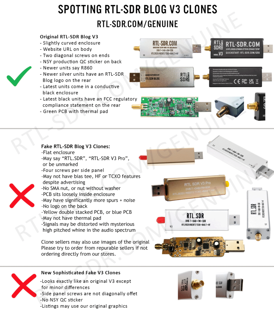
RTL-SDR Blog V3 Counterfeit Warning!

If you have purchased a counterfeit RTL-SDR Blog V3 device the features described in this guide may not work correctly, if at all. If you were tricked into thinking it was an original RTL-SDR Blog V3, please lodge a dispute with the marketplace platform purchased from. 

Please purchase either directly from our store, or using the links on the store to official marketplace listings or resellers.

Version 3 of our customized RTL-SDR dongles brought out some new interesting features. In this guide we explain how to use those feature. If you are interested, we also have the V3 feature datasheet available here.

We reccomend using our RTL-SDR Blog driver fork here https://github.com/rtlsdrblog/rtl-sdr-blog. Note that SDR# already installs this driver by default when you run install-rtlsdr.bat as described in the quickstart guide.

Feature 1: Direct Sampling HF Mode

This feature allows you to listen to HF signals between about 500 kHz to 28.8 MHz.

To use direct sampling mode:

  1. If you are using our RTL-SDR Blog driver fork, there is nothing to do. Just tune down below 28.8 MHz, and direct sampling will automatically be activated.

For other drivers:

  1. Connect an appropriate HF antenna to the SMA antenna port (this is the same port where you connect your VHF/UHF antenna). 
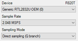
  2. In SDR# select the Q-branch in the configure menu (the cog icon next to the play button). (If it is greyed out make sure you stop the SDR first, by clicking the stop button in SDR#)
  3. Press Play and tune to 500 kHz - 28.8 MHz.

Q-branch

VHF antennas like small discones or short whip antennas will probably not pick up HF signals very well, if at all. If you have one of our dipole antennas, try connecting a long 5 meter or longer wire to the element connected to the coax center wire. To check which element is connected to the center coax you can open the lid on the black dipole base. Ideally you should use a 9:1 unun with the long wire antenna for optimal reception. Even more ideally you'd use an antenna tuner, though this is expensive.

We can also highly recommend the use of low cost active magnetic loop antennas like the MLA30+.

MW Attenuation Curve Note: In newer RTL-SDR Blog V3 batches the attenuation curve for direct sampling has been tweaked in order to provide greater attenuation in the MW band (below 2 MHz). The reason for this is that many users experience severe overload from strong broadcast AM stations which can cause problems with reception above 2 MHz.

The result is that reception of the MW broadcast AM band will be poorer, but reception above 2 MHz could be improved in many cases where overload was present before. However, reception on the MW bands with an appropriate HF antenna even with the attenuation is not usually a problem due to their extreme high power and local location.

HDSDR/GQRX and Other Software

Other software like HDSDR and GQRX can also support direct sampling. It may entail setting a device string, and for the Q-branch, the value should be 2 (or sometimes 3). In GQRX the device string would be "rtl=0,direct_samp=2" (without the quotes). In some installs that use different drivers it may be "rtl=0,direct_samp=3" instead. Make sure that there is no space after the comma. SDR-Touch on Android has a direct sampling option available in its settings page.

To go back to listening to frequencies above 28.8 MHz remember to change the sampling mode back to "Quadrature Sampling".

Note that this feature makes use of direct sampling and so aliasing will occur. The RTL-SDR ADC samples at 28.8 MHz, thus you may see mirrors of strong signals from 0 - 14.4 MHz while tuning to 14.4 - 28.8 MHz and the other way around as well. To remove these images you need to use a low pass filter for 0 - 14.4 MHz, and a high pass filter for 14.4 - 28.8 MHz, or simply filter your band of interest. (Note that that 28.8 MHz is downsampled on chip resulting in the 3.2 MHz bandwidth)

Modified rtl_tcp for direct sampling

The standard Osmocom version of rtl_tcp only allows for direct sampling on the I-branch, which is useless as we need direct sampling on the Q-branch. Please see our RTL-SDR-Blog Drivers for a version that includes a -D direct sampling flag. The Releases page has a Windows release.

Forcing Direct Sampling To be Always ON

This feature is now disabled and superseded by the feature that automatically activates direct sampling mode when the frequency is set below 28.8 MHz.

Feature 2: Software Selectable Bias Tee

V.1. and V.2. of our dongles included a bias tee which could manually be enabled by opening the case and soldering two pads on the PCB together. V.3. introduces a 4.5V bias tee that can be toggled entirely in software. The bias tee can continuously pull up to 180 mA of current.

WARNING: Before using the bias tee please ensure that you understand that you should not use this option when the dongle is connected directly to a DC short circuited antenna unless you are using an LNA. Although the bias tee circuit is dual protected against accidental shorts with a thermal self-resetting fuse and overcurrent protection on the LDO, short circuiting the bias tee for an extended period of time (days) could damage the LDO or fuse permanently. Only use it while connected to an actual powered device, like an LNA, active antenna or the SpyVerter.

To make things clearer: DC Short Antenna -> LNA -> Coax -> V3(bias tee on) is absolutely fine. What's not good and makes no sense anyway is DC Short Antenna -> Coax -> V3(bias tee on). DC Short Antenna -> Coax -> V3(bias tee off) is fine.

Note that the legacy DVB-T TV drivers will activate the bias tee by default. On Linux ensure that you have properly blacklisted the DVB-T drivers. More info on how to blacklist on the Linux section on the quickstart guide.

Optional Video: Bias tee tutorial by SignalsEverywhere available here.

To enable the bias tee in Windows:

  1. Download and extract all the files in this zip file to a folder on your PC. It contains two batch files that can be run.
  2. Make sure all SDR software like SDR#/HDSDR/SDR-Console etc is fully closed.
  3. Run the biastee_on.bat file to turn the bias tee on. It will run and open a CMD prompt that will briefly say "Found Rafael Micro R820T Tuner". The CMD prompt will close soon after upon success.
  4. The bias tee is now on. To turn it off repeat steps 2 & 3, but instead run the biastee_off.bat batch file. Alternatively, simply disconnect and then reconnect the SDR to turn the bias tee off.

If you have multiple dongles connected you'll need to edit the batch file to specify what dongle's bias tee you want to activate. Open the bat file with any text editor, like Notepad, and add the dongle selector "-d" flag. For example to activate the bias tee on the dongle that was plugged in second you'd need to change it to "rtl_biast -b 1 -d 1".

If you get a Smart Screen message, click on More Info, and then on Run Anyway. Also note that some versions of Windows may fail to run batch files due to misconfiguration or aggressive antivirus software. If you cannot fix these problems with Windows or your antivirus, run the command manually on the CMD line.

To run it manually on the CMD line first browse to the directory where the bias tee software is stored using "cd" (e.g. cd C:\SDR\bias_tee_folder), and then run:

  1. ON: rtl_biast -b 1
  2. OFF: rtl_biast -b 0
  3. If needed select a particular RTL-SDR device with the -d flag.

To enable the bias tee in Linux:

In Linux or MacOS download the source from git, compile it the same way you do the regular RTL-SDR drivers, and then run ./rtl_biast -b 1 to turn the bias tee on and ./rtl_biast -b 0 to turn the bias tee off. The procedure is:

git clone https://github.com/rtlsdrblog/rtl-sdr-blog
cd rtl-sdr-blog
mkdir build
cd build
cmake .. -DDETACH_KERNEL_DRIVER=ON
make
cd src
./rtl_biast -b 1

If you want to be able to run the bias tee program from anywhere on the command line you can also run "sudo make install".

If you have trouble running the bias tee check with a multimeter if there is 4.5V at the SMA port. Also check that your powered device is actually capable of receiving power. Remember that not all LNA's can accept bias tee power. We recommend Adam 9A4QV's LNA4ALL, as you can order this from his store with the bias tee power option enabled. If you need further help please contact us at [email protected].

Enabling the Bias Tee in PiAware

Please see this link for instructions, or see below to see how to force the bias tee to be always on.

Forcing the Bias Tee to be Always On

If you are using our RTL-SDR-Blog driver branch you can force the bias tee to be always on by setting a flag in the EEPROM. The rtl_eeprom command is "rtl_eeprom -b 1". Run the opposite command "rtl_eeprom -b 0" to disable the forced bias tee.

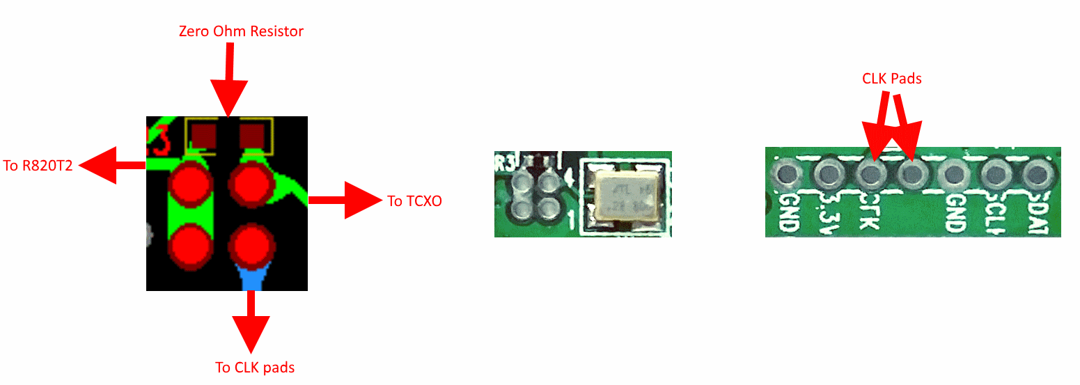
Feature 3: Selectable Clock & Expansion Headers

This is for advanced users who need to daisy chain clocks together for coherent experiments, or need to access other ports. You can either bridge the clock selector the directly with a solder bridge, or solder on a 1.27mm 2x2 header pin jumper.

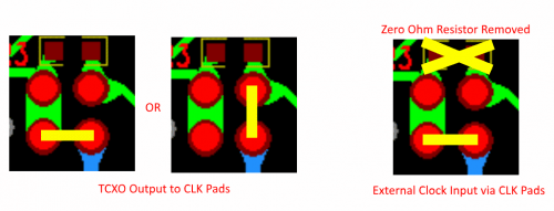
To add a jumper to the CLK selector header.

  1. Carefully remove the 0 Ohm resistor.
  2. Very carefully solder a 1.27mm 2x2 header onto the clock selector pads.
  3. You can now select your clock input.

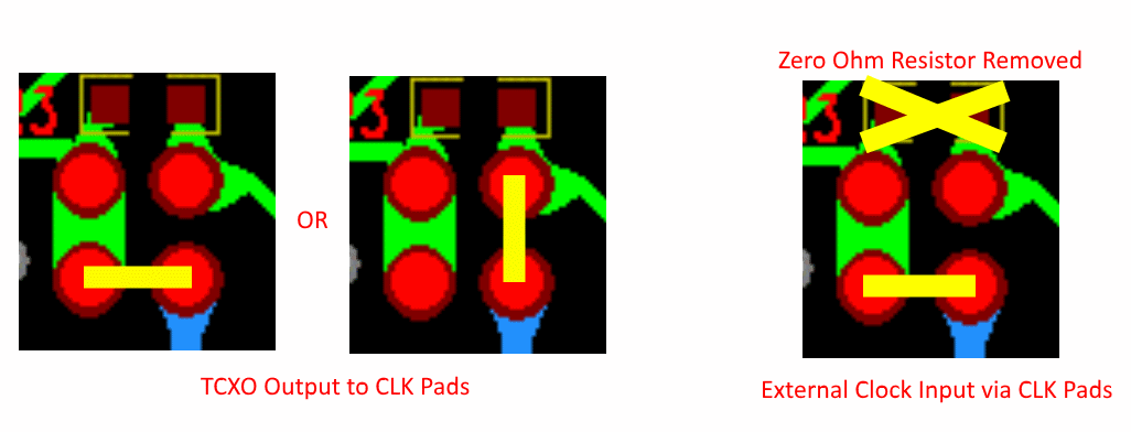
How to connect the CLK jumpers:

CLK_1

 The first position allows you to output the dongles clock to the CLK pads. The second position allows you to input an external clock.

CLK2

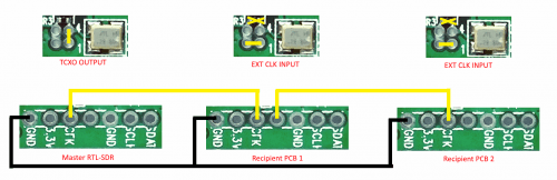
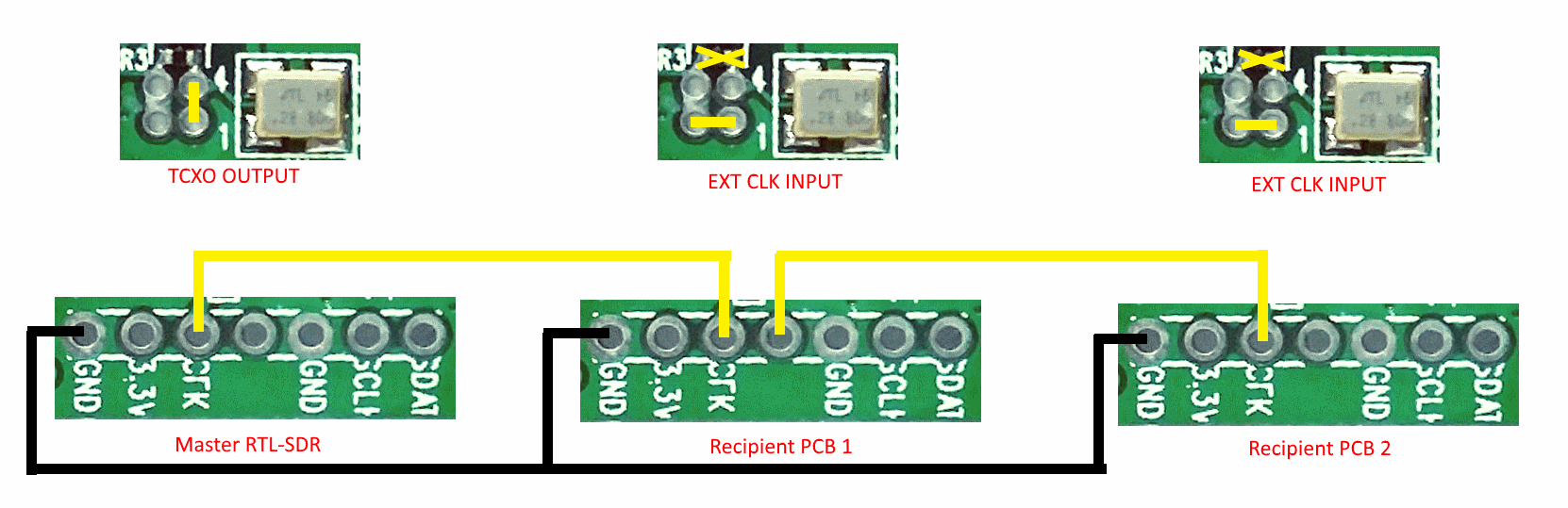
An example of CLK daisy chaining is shown below. One dongles TCXO is connected to two other dongles who have disconnected clocks.

CLK3

Feature 4: Additional GPIO Ports

Please see the guide written by Rodrigo Freire here.

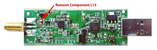
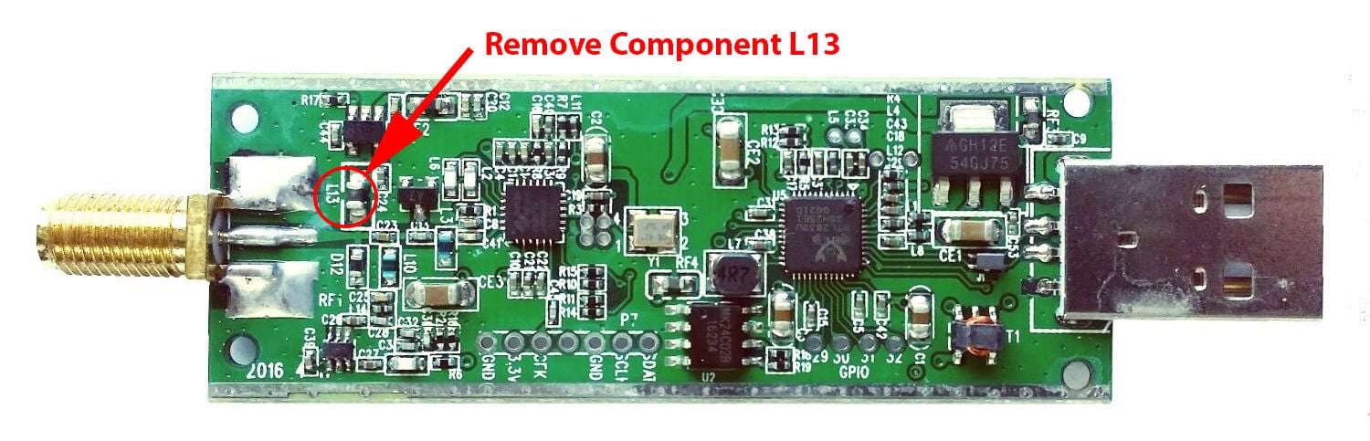
LF/MF Improvement / Bias Tee Disable Mod:

If you want to improve the performance at LF/MF (below 500 kHz) and do not require the bias tee, then you can remove the bias tee inductor at L13. Of course remember that if you are interested in VLF/LF, it might be a better idea to use an upconverter like the SpyVerter, which can be powered by the bias tee on the dongle.

Notes to be aware of:

I opened my RTL-SDR V3 dongle and found that the thermal pad has a small air gap between it and the enclosure, is this normal?

This is normal. The purpose of the thermal pad is to fix L-band VCO lock problem that are related to PCB heat build up. The RTL-SDR V3 only requires very minor heat sinking to overcome this issue, and a small air gap does not reduce the thermal transfer enough to cause issues. In fact the V3 PCB has already been redesigned to dissipate heat better, so the thermal pad is not strictly required, except in very warm climates.

My RTL-SDR V3 is getting hot.

Please remember that these units do get hot to the touch especially when used in warm climates. This is not an issue and is normal. The temperature will normally be about 20 - 25C above ambient. We have improved the thermal bonding and heat transfer between the chips and the metal case. This results in making the metal case hotter, but it keeps the chips much cooler, resulting in better performance. To lengthen the life of the dongle we recommend keeping the unit away from direct hot sunlight.

Current Known Issues:

We're constantly trying to improve our units and we always make note of what issues exist and how to fix them.

2019 Onwards:

No known issues.

2019 and earlier units (no longer shipping):

Note that the following problem has been fixed in newer batches with a new design.

0.2 - 0.3% of units may have a faulty RTL2832U chip. This is characterized by higher than normal USB currents (normal is 0.28A - 0.3A), and often random disconnections from the USB as well as increased heat. The same problem affects all brands of RTL-SDR.

2018/8 Batch (no longer shipping):

A small number of these units (~approx 300 units) had faulty bias tee LDO chips which caused the bias tee to be permanently on. The cause was bad silicon in the LDO chip. These units run normally in all other ways, except that the bias tee cannot be turned off. They can continue to be used normally, without the bias tee. The thermal fuse will protect against short circuits.

If you have one of these, feel free to contact us at [email protected] for a replacement, or if the bias tee is not important to you and you can solder, removing the L13 inductor will fully disable the bias tee.  

Known V3 Batch 1 Issues (limited quantity batch, no longer shipping):

  1. Increased sideband noise on very strong narrowband signals. This should not be a significant problem as it only affects very strong signals. The hardware fix is to add about 100-220uF of capacitance on the 3.3V power line. Batch 2 will reduce this noise.
  2. The bias tee when turned on adds a large spur in direct sampling HF mode. This may be problematic only if you intend to use a bias tee powered HF LNA in direct sampling mode. This can be fixed by adding about 2.2uF of capacitance to the output of the LDO, before the inductor. Batch 2 will fix this.
  3. The bias tee can be damaged by accidentally short circuiting the output for a few seconds while it is on. This damage only occurs on USB3.0 and USB2.0 ports that can provide up to 1A or more or current. Batch 2 will add a resettable fuse to prevent damage.


New RTL-SDR Blog Units Now Available in Store: HF via Direct Sampling, Software Switchable Bias Tee, Less Noise/Spurs

A few months ago we brought out a poll asking readers of this blog what they might like to see in a revised RTL-SDR dongle. We’ve now taken some of those suggestions and implemented them into a brand new dongle. For now the price of the new dongle will remain the same as before at $24.95 USD for the dongle + antenna kit and $19.95 USD for the dongle only, but we may need to increase the price by $1 – $2 within the next few weeks due to our slightly increased manufacturing costs. Worldwide shipping remains free from the Chinese international warehouse, and US customers can order either from the Chinese international warehouse or from Amazon who will give you free shipping if you are a Prime member, or spend over $49. The Chinese warehouse is currently stocked and ready to ship, and Amazon is now stocked and should be ready to ship by the end of this week.

Please go to our store page at rtl-sdr.com/store for information on purchasing.

RTLSDR_Front

RTLSDR_PCB

Here is the short version of the biggest changes:

1) HF support via direct sampling. Connect an HF antenna directly to the SMA connector and tune from 500 kHz – 24 MHz with the direct sampling mod. (No hardware modding or soldering required)
2) Lower internal noise. Less spurs, lower noise floor etc.
3) Software switchable bias tee. No need to do any soldering to enable the bias tee. Can be turned on and off in software.

We call this version three of our RTL-SDR Blog dongles. The first was version zero and was simply the standard MCX dongles with better antennas. Next came version 1 with the bias tee and SMA connector, and version two introduced the metal case.

Here is the long list of improvements and changes, and why they were made:

1) Improved ESD protection on the radio front end. The BAV99 diode which is used on most dongles is not a true ESD rated diode. We have added a real ESD rated diode for better protection. The BAV99 remains in the circuit as a strong signal clipper, to prevent damage to the R820T2 from overly strong signals. Please remember that not even this will save your radio from a lightning strike, and any permanently outdoor mounted antenna system must have its own lightning protection.

2) Longer SMA connector. One or two customers had problems with the shorter SMA plugs which could not fit some of their antenna connectors. The longer shaft fixes this and also allows us to add a nut to fasten it to the aluminum body which provides a better low impedance connection (although this is not strictly needed as the PCB side ground tracks already provide a good connection).

3) Improved front end circuit. The standard matching circuit on the RTL-SDR was designed for DVB-T use, and tends to attenuate signals above ~1 GHz. The new matching circuit has less attenuation above 1 GHz and similar performance below. We used very high quality, high SRF, high Q inductors in this circuit.

4) Added a software switchable 4.5v bias tee. In previous versions of our units the 4.5v bias tee needed to be activated manually, by soldering a bridge between two pads on the PCB. However we found that many customers who want to use the bias tee do not have the skills or tools to be able to perform this mod. The new unit makes use of a low noise LDO and one of the GPIO pins on the RTL2832U to activate the bias tee in software. This of course requires a modification to the drivers, but we will shortly upload a program called rtl_biast and batch files (available now) to turn the bias tee on and off in Windows and Linux.

This bias tee is great for powering a remote LNA (like Adams PSA5043+ based LNA4ALL) or something like the SpyVerter upconverter. We’ve tested it with both and found them to be running just fine. 

Warning: The bias tee LDO can be damaged if you short circuit it. Before turning on the bias tee, ensure the circuit to be powered is not shorted, or that the RTL-SDR is not connected to a DC shorted antenna!

5) Added several access pads on the PCB. Access pads for the unused GPIO pins, CLK in/out, 3.3V, GND and I2C pins have been added. The CLK input/output is disconnected by default (see change 6). Access pads for the I branch have also been added as some users and industrial customers are using these in special projects. These pads are only for advanced users who need them for special projects. Take care as these pins are not ESD protected.

6) Added a clock selector jumper. By soldering in a 4 pin 1.27mm pitch jumper header and removing the default 0 Ohm resistor, one can now easily select between the onboard clock, an external clock, or having the on board clock be the output for another dongle. This is for advanced users only who want to experiment with things like passive radar, and coherent receivers.

7) Reduced noise with a modified PCB design. This significantly reduces spurs and noise pickup due much lower impedance grounding and blocking of interference. Also added a USB common mode choke to reduce USB noise, several ferrite chokes on the PCB, and a lower noise LDO. A larger ground plane also improves on heat dissipation. 

8) Added an experimental HF direct sampling circuit, which is diplexed out from the SMA connector. This has little to no effect on VHF/UHF operation, but allows us to make use of the Q branch on the RTL2832U chip for direct sampling, which allows us to receive from about 500 kHz to about 24 MHz. (Below 500 kHz is unavailable due to attenuation from the bias tee circuit). We used a ~10dB 50 Ohm preamp as a buffer and to overcome losses in the transformer and filter. We also added a strong 24 MHz low pass filter, and added an impedance matching transformer coil to ensure good direct sampling performance.

Of course direct sampling can never be as good as using an upconverter. It can overload easily if you have strong signals since there is no gain control. And you will see aliasing of signals above 14.4 MHz due to Nyquist. But this should at least give the majority of users a decent taste of what’s on HF. If you then find HF interesting, then you can consider upgrading to an upconverter like the SpyVerter (and the SpyVerter is of course compatible with our bias tee for easy operation).

We’re still classing this mode as experimental (and will be interested to hear any feedback on results), but we have had good results in our testing of this mode when receiving signals that are not too strong, getting sensitivity as good as an upconverter. We found that very good reception was obtainable with a long wire antenna and 9:1 unun combination.

9) Antenna bases now come with a stronger magnet and a conductive copper sticker on the bottom. The stronger magnet adds very good stability when using our large 1.5m antenna and the copper sticker ensures that good electrical contact can be made between the base and whatever piece of metal you use underneath as the ground plane. This significantly improves the antenna’s performance as a quarter wave ground plane.

Ant_base_copper

10) Added corner mounting holes for those who want to stack PCBs. Some customers have been building devices that require multiple RTL-SDR dongles, and these standoff holes should aid in stacking.

As from the previous innovations the units still come with:

1) SMA connector – The most common connector in the radio world. Easy to adapt to other connectors and low loss over a wide range of frequencies.
2) Thermal pad – A thin thermal pad allows heat to transfer from the PCB to the metal case easily. The metal case then cools off to the surrounding air. This helps to solve L-band insensitivity problems.
3) Metal case – Helps block out interference and provides cooling.

We now have a V3 users guide available which explains how to use the new features such as the bias tee, HF mode and CLK jumpers.

What’s coming next?

We think that our unit is now pretty much at the peak of how good a cheap R820T2 RTL-SDR can be, so apart from minor tweaks this is likely to be our last major revision of this model of the RTL-SDR. In a 1-2 months we hope to bring out a FM bandstop filter with metal enclosure and SMA plugs with a target cost of $14.95 shipped. Further into the future we also hope to bring out supporting products like a wideband bias tee powered LNA and wideband antennas. These supporting products will of course be compatible with other SDR’s like the Airspy or SDRplay, or other RTL-SDR dongles.


RTLSDR_Profile

HamRadioScience: Why Apple’s iMac May be the Best PC for SDR Applications

Over on on the HamRadioScience blog, the author has uploaded an article that makes the case on why Apple iMac PC’s may be the best choice for SDR receivers (at least for HF frequencies). In the testing he uses an SDRplay and Elad FM-Duo to show that the plastic case of the SDRplay does not affect the picked up RFI. He shows that when the SDR’s are connected to an iMac the interference from RFI on HF frequencies is minimal. However when connected to a Core i5 PC, there is significant amounts of CPU and monitor noise generated.

The differences in generated noise probably come from the fact that the iMac is probably much better shielded with an aluminum case and that they have high build quality standards for their monitors. The author suggests that an alternative to using an iMac could be to build your own PC, ensuring that dual chamber metal enclosures are used, which ensures that the power supply is isolated in its own separate steel compartment.

RFI is visible with the SDRplay in SDRuno when using the PC. But no RFI is seen with the iMac.

An AIS Decoder for MATLAB and the RTL-SDR

RTL-SDR.com reader Mike wrote in to us today to let us know that he has released his AIS decoder for MATLAB and the RTL-SDR. MATLAB is a technical computing language used by many scientists and engineers in the world. Mike writes the following about his work:

Automatic Identification System (AIS) is a communication standard that is used by commercial and recreational maritime vessels to report a ship’s ID, position, course and other information. This data is used for collision avoidance, search and rescue and many other applications. AIS has the following characteristics:

  • Access protocol: Self-organizing Time Division Multiple Access (SOTDMA)
  • Transmission frequencies: 161.975 MHz and 162.025 MHz
  • Transmit Power: 2 W or 12.5 W
  • Modulation: Gaussian Minimum Shift Keying (GMSK)
  • Data Rate: 9600 bits per second

An AIS decoder that uses the RTL-SDR and MATLAB to capture AIS transmissions is posted on MATLAB Central, the MathWorks file sharing exchange. The decoder has three main components

  1. Software to connect MATLAB to the RTL-SDR and bring IQ data directly into the MATLAB workspace (http://www.mathworks.com/hardware-support/rtl-sdr.html)
  2. Demodulation and decoding algorithms to convert the IQ samples into bits and decode the AIS data (http://www.mathworks.com/products/communications/)
  3. A user interface to configure the RTL-SDR, launch the capture and decoding process, and display the decoded messages (http://www.mathworks.com/matlabcentral/fileexchange/57600-ais-decoder)

The MATLAB Central post includes MATLAB source code for the AIS decoder, captured data files from Boston and San Francisco, an app for easy configuration and operation of the decoder, and instructions for installing the RTL-SDR Hardware Support Package and AIS Decoder app.

If you want to learn how AIS works, and how to write a decoder, then a MATLAB example like this is an excellent resource.

Unlocking Almost Any Vehicle with an SDR or Arduino

Earlier this week wired.com released a story indicating that researchers from the University of Birmingham have discovered two vulnerabilities that can be used to unlock almost any car. The first vulnerability concerns Volkswagen Group vehicles (VW, Audi, SEAT, Skoda) sold since 1995. Essentially their research found that the keyless entry systems of VW Group vehicles relies only on a few global master keys which they have been able to recover through reverse engineering of an undisclosed component used in a VW car. Then by sniffing the wireless key’s signal with an RF module or SDR like the RTL-SDR or HackRF they are able to recover the cryptographic algorithms used and then using the global key clone the wireless key signal, which can then be re-transmitted with a simple Arduino.

In their second research findings, the researcher’s write how they have been able to crack the Hitag2 rolling code system which is used in many vehicles such as Alfa Romeo, Chevrolet, Citroen, Dacia, Fiat, Ford, Lancia, Mitsubishi, Nissan, Opel, Peugot and Renault. Again, the hack works by sniffing a few wireless keyfob rolling code signals with an SDR or other device. Once the signals have been sniffed a simple laptop computer can reportedly break the encryption within one minute.

Here are some interesting excerpts from the conclusions of the paper:

The results of this paper show that major manufacturers have used insecure schemes over more than 20 years. Due to the widespread use of the analyzed systems, our findings have worldwide impact. Owners of affected vehicles should be aware that unlocking the doors of their car is much simpler than commonly assumed today. Both for the VW Group and the Hitag2 rolling code schemes, it is possible to clone the original remote control and gain unauthorized access to the vehicle after eavesdropping one or a few rolling codes, respectively. The necessary equipment to receive and send rolling codes, for example SDRs like the USRP or HackRF and off-the-shelf RF modules like the TI Chronos smart watch, are widely available at low cost.

A successful attack on the RKE and anti-theft system would also enable or facilitate other crimes:

– theft of the vehicle itself by circumventing the immobilizer system or by programming a new key into the car via the OBD port with a suitable tool

– compromising the board computer of a modern vehicle, which may even affect personal safety, e.g., by deactivating the brakes while switching on the wiping system in a bend

– inconspicuously placing an object or a person inside the car. The car could be locked again after the act

– on-the-road robbery, affecting the personal safety of the driver or passengers if they (incorrectly) assume that the vehicle is securely locked

Note that due to the long range of RKE systems it is technically feasible to eavesdrop the signals of all cars on a parking lot or at a car dealer by placing an eavesdropping device there overnight. Afterwards, all vulnerable cars could be opened by the adversary. Practical experiments suggest that the receiving ranges can be substantially increased: The authors of [18] report eavesdropping of a 433 MHz RFID system, with technology comparable to RKE, from up to 1 km using low-cost equipment.

The findings were presented at the Usenix Advanced Computing Systems Association conference during August 10-12, 2016 in Austin, TX. The white paper is titled “Lock It and Still Lose It—On the (In)Security of Automotive Remote Keyless Entry Systems” and can be downloaded here. Of course they did not publish the actual VW master keys in their paper and they have notified VW and NXP who make the Hitag2 chips in advance, noting that Hitag2 had actually been broken for several years prior.

Back in February we showed how Smay Kamkar was able to bypass rolling codes with his RollJam device, however the findings by these researcher’s is different in that they are actually able to generate new rolling codes, such that a simple Arduino with transmitter can act as a second wireless remote.

A $40 Arduino which can be used to record wireless rolling codes, then transmit new ones once cracked.
A $40 Arduino which can be used to record wireless rolling codes, then transmit new ones once the encryption has been broken.

New Outernet Products For Sale: E4000 RTL-SDR, L-Band Patch Antenna, L-Band LNA

Outernet is a new satellite service that aims to be a free “library in the sky”. They continuously broadcast services such as news, weather, videos and other files from satellites. Their aim is to provide up to date information to users in locations with little to no internet (rural, third world and sea), or in countries with censored internet. It may also be of interest to disaster preppers. Currently they have an active Ku (12 – 18 GHz, though due to be discontinued shortly) and C-band (4 – 8 GHz) satellite service, and now recently have their L-band (1.5 GHz) service active. The L-band signal is currently broadcasting at 1539.8725 MHz over the Americas, 1545.525 MHz over Europe/Africa/India and 1545.9525 MHz over Asia/Pacific.

To receive their L-Band service you will need an RTL-SDR capable of receiving 1.5 GHz, like a R820T/2 RTL-SDR (preferably at least passively cooled like our RTL-SDR Blog models as some R820T/2 units tend to fail at 1.5 GHz without cooling) or an E4000 dongle. You will also need an appropriate L-Band antenna and L-Band amplifier.

To help with these hardware requirements, Outernet have just released for sale an E4000 RTL-SDR with bias tee enabled ($39), an L-band satellite patch antenna ($24) and an L-Band LNA ($19). There is also a E4000 + LNA bundle ($49) available. The E4000 comes in a metal case, and has the bias tee always on. The LNA requires bias tee power and is also compatible with our RTL-SDR Blog units that have the bias tee. The patch antenna is tuned for 1525 – 1559 MHz and is the production version of the prototype antenna we used in our Inmarsat STD-C tutorial. Combined with an LNA we found that the patch antenna gives good performance and can also be used to receive other services such as Inmarsat STD-C and AERO. Currently shipping is only available within the USA, but they write that they will have international shipping available shortly.

EDIT: For international buyers the Outernet store is now started selling these products at http://store.outernet.is.

The L-Band Outernet signal decoders aren’t finalized yet, but we expect them to be released in a matter of days to weeks. They will have decoders available for the $9 CHIP computer and Raspberry Pi 3 platforms. They way it works is that you plug your RTL-SDR with L-band LNA and patch antenna connected into the CHIP or Raspberry Pi 3 which is running their customized image. The CHIP/Pi3 then broadcasts a WiFi access point which you can then connect to with any device, and access the files as they are downloaded. Once these decoders are released we’ll do a full tutorial on receiving the Outernet L-Band service with an RTL-SDR.

The Outernet L-Band Patch Antenna
The Outnernet L-Band LNA
The Outernet L-Band LNA
The Outernet E4000 RTL-SDR in metal case with bias tee.