Category: RTL-SDR

Passively Cooling the RTL-SDR with a Thermal Gap Pad

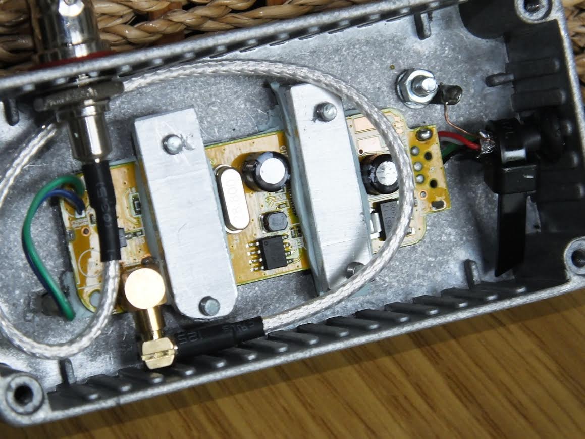
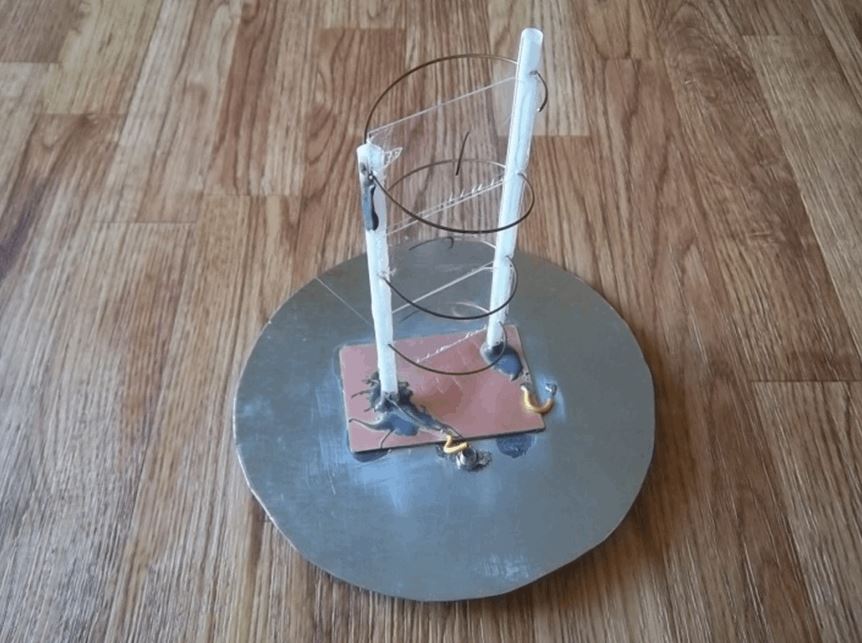
John Mills recently wrote in to us at RTL-SDR.com to show us how he cools his RTL-SDR by using a thermal gap pad stuck to the entire bottom of the RTL-SDR PCB. A thermal gap pad is a soft pliable material that is often used to interface between electronic chips and heatsinks. The gap pad forms into tight hard to reach spaces and conducts heat towards the heatsink. It is not electrically conductive, so the entire bottom of the RTL-SDR can be stuck to the thermal gap pad, which is then stuck to a metal heat sink.

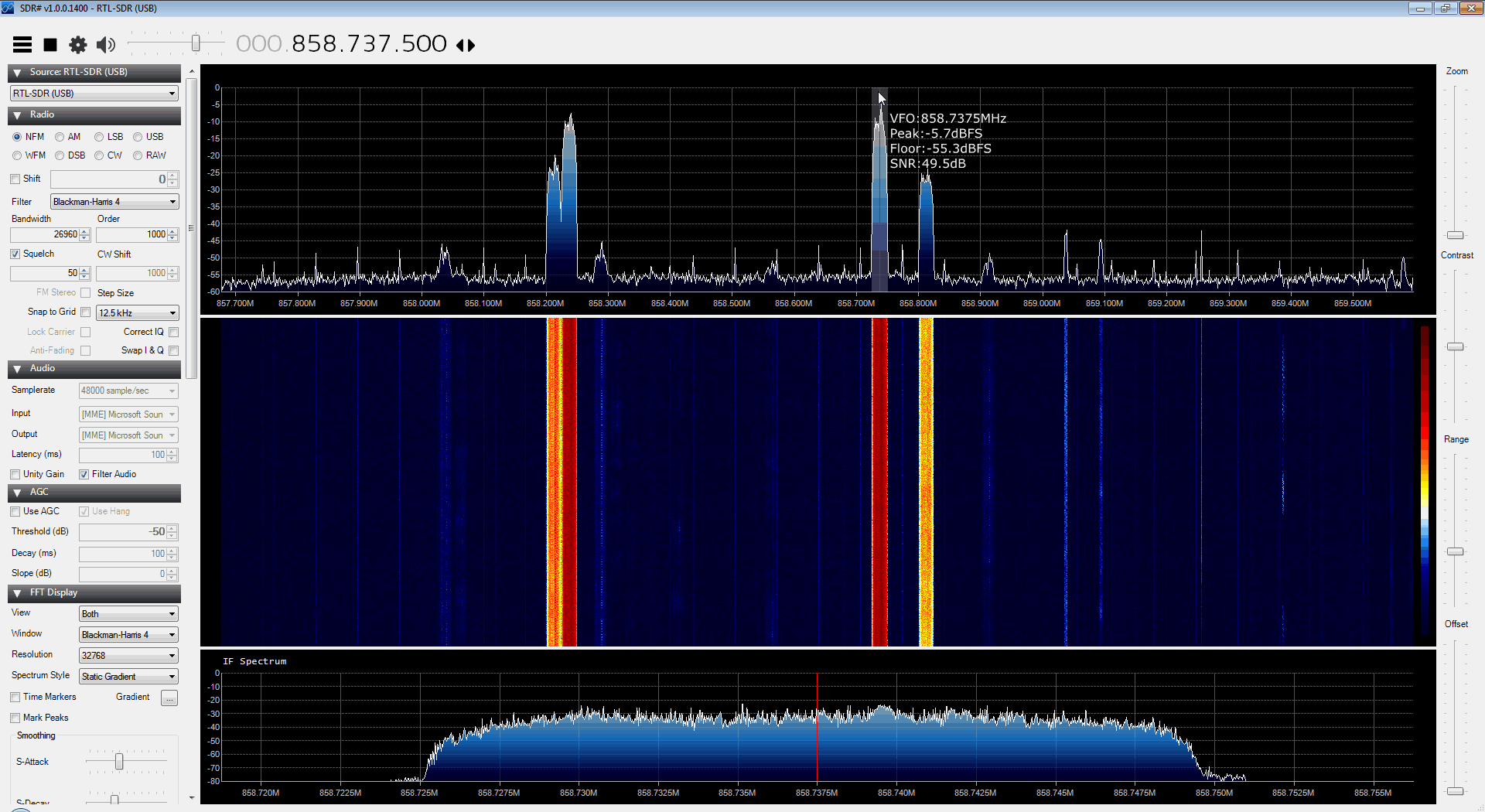
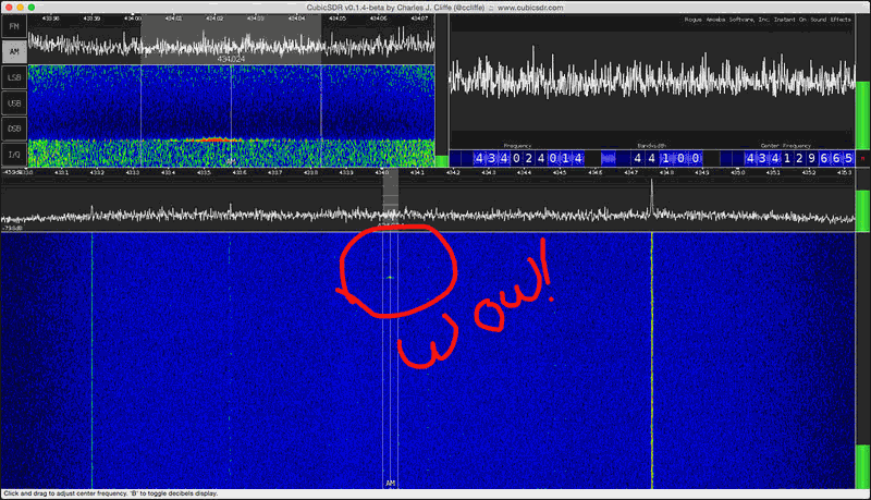
John uses a thermal gap pad made by Bergquist, with part number GP5000S35-0.100-02. This gap pad is 0.1 inches thick, is easily cut with a craft knife and is tacky so it easily sticks to the heatsink and RTL-SDR PCB. It has a thermal conductivity of 5W/m.k. John uses the pad to help to cool the R820T, RTL2832U and voltage regulator chips. It has been shown in some previous posts that by cooling the R820T chip increased sensitivity can be obtained, especially at frequencies above 1.2 GHz.

He writes that if there is sufficient interest then he may consider selling strips of it on eBay. You can contact him at sdr_AT_milairuk.co.uk.

Below we’ve posted images of Johns thermal pad cooled RTL-SDR’s, along with his comments on them in the captions.

Inside latest SDR / Latest SDR - "This is my latest version using a R820T2 version, and I have also fitted this with a TCXO. In this version I also used a 1Mohm and 47nF to ground the USB shield wire as in a previous post. This version only uses one metal spacer and the end  of the PCB is secured by two M2 nylon screws / nuts. Case from China RF on Ebay."
Open SDR – “Just held onto a heatsink with two pieces of string ! Then this sits on another larger heatsink using another piece of Gap Pad to hold it – this has been working in my garden shed now for over 2 years feeding ADSB data”
Diecast Box SDR – "in this one I have made two small threaded metal clamps, lined with gap pad and tightened just enough to keep the PCB in good contact with the gap pad underneath and the diecast box. I use small BNC to MCX pigtails off Ebay to connect to the antenna socket. I also remove the LED and place through the box as can be seen."
Diecast Box SDR – “in this one I have made two small threaded metal clamps, lined with gap pad and tightened just enough to keep the PCB in good contact with the gap pad underneath and the diecast box. I use small BNC to MCX pigtails off Ebay to connect to the antenna socket. I also remove the LED and place through the box as can be seen.”
Inside latest SDR / Latest SDR - "This is my latest version using a R820T2 version, and I have also fitted this with a TCXO. In this version I also used a 1Mohm and 47nF to ground the USB shield wire as in a previous post. This version only uses one metal spacer and the end  of the PCB is secured by two M2 nylon screws / nuts. Case from China RF on Ebay."
Inside latest SDR / Latest SDR – “This is my latest version using a R820T2 version, and I have also fitted this with a TCXO. In this version I also used a 1Mohm and 47nF to ground the USB shield wire as in a previous post. This version only uses one metal spacer and the end of the PCB is secured by two M2 nylon screws / nuts. Case from China RF on Ebay.”
Latest SDR - Outside
Latest SDR – Outside

Comparing RTL-SDR’s on L-Band Reception, Tuner Temperatures and Passive Cooling

Over on Reddit user MaxWorm has been doing some experiments with comparing various RTL-SDR dongles on L-band (1 – 2 GHz) reception. Previously we wrote a tutorial on decoding Inmarsat signals which are at around 1.5 GHz and noted that the R802T/2 dongles can have some trouble at these frequencies.

It is known that the R820T/2 is not as good as the older now rare and expensive E4000 tuners at frequencies above 1.5 GHz, and it is also known that sensitivity decreases as the temperature of the R820T/2 increases, especially at frequencies above 1.5 GHz.

MaxWorm tested an R820T, R820T2 and two E4000 sticks at receiving L-band frequencies. He found that one of the E4000’s performed the best, but surprisingly the other E4000 dongle was totally deaf in the L-band. The R820T and R820T2 dongles performed similarly – not as good as the best E4000, but not as bad as the worst. All tuners exhibited reduced signal strength when warm.

In another post MaxWorm also measured the temperature of the tuner chips in each of his units, and created a simple heatsink for one of his R820T2 dongles. His results show that the heatsink passive cooling works well, significantly cooling the R820T2 chip. His measurements are copied below:

R820T2 in Plastic case:
R820T2: 77°C top / 74°C bottom
RTL2832: 56°C top / 54°C bottom

R820T2 bare PCB:
R820T2: 62°C top / 63°C bottom
RTL2832: 43°C top / 42°C bottom

R820T2 in Alu-Case with Alu “L-Bridge” on Tuner:
R820T2: top 37°C / bottom 47°C
RTL2832: top 49°C / bottom 40°C

E4000 in plastic case:
E4000: 37°C top / 37°C bottom
RTL2832: 46°C top / 40°C bottom

bare E4000 PCB:
E4000: 37°C top / 32°C bottom
RTL2832: 40°C top / 37°C bottom

Other experimenters have previously applied fan cooling and oil cooling to RTL-SDR dongles to cool them and increase sensitivity.

RTL-SDR with heat sink to aluminium case.
RTL-SDR with heat sink on the R820T2 chip connectoed to the aluminium case.
L-Band Reception Results for an R820T, R820T2 and two E4000 dongles.

SDR# updated to revision 1400 & SDR Touch updated to V2.6

The popular SDR# software which is often used together with RTL-SDR dongles has recently been updated to revision 1400. This new revision brings an interesting new feature which automatically estimates and displays the peak, floor and signal to noise ratio (SNR) values of the currently tuned bandwidth. Watching the SNR metric is very useful when tuning the RF gain settings, as best reception is obtained when the SNR value is maximised. The author also writes that there have been several radical changes to the code that leverage the latest .Net 4.6 framework which should improve the signal processing quality, CPU usage, user experience and hardware support. The changelog is pasted below:

Enhanced the Center tuning mode and extended it for RTL-SDR;
Enhanced the spectrum display;
Changed the frequency labelling to use multiples of 2.5/5/10 or frequency steps;
Added Peak, Floor and SNR estimation for the selection;
Enhanced the defaults for better user experience;

We note that some plugins may break with this update so be sure to make a backup if upgrading. Vasili, one of the most active SDR# plugin programmers has updated most of his plugins to work on this new version now.

Revision 1400 of SDR# with SNR estimation.

In addition to this update, over on the Android OS the popular mobile app SDRTouch has been updated to version 2.6. This new version brings the following features and improvements:

  • Baseband recording and file playback
  • Direct sampling support for full-band receivers
  • Improved SSB image rejection
  • Fixed tuning step
  • Manual filter bandwidth
  • Improved accessibility
  • Bug fixes

Reverse engineering a wireless thermostat with an RTL-SDR

When Tom Taylors home heating boiler was replaced the builders also replaced the old wired rotary thermostat with a digital wireless one. It sounds good, but Tom soon discovered that the thermostat UI was terrible and that the buttons were horrible to press, making him prefer to shiver in the cold. So Tom decided to see if there was a smarter way to control the heating.

When Tom investigated the thermostat, he discovered that the wireless unit transmitted in the unlicensed 433 MHz band and that the thermostat only transmitted two commands, turn on or turn off. By using his RTL-SDR and the CubicSDR software on his Mac he was able to detect the short blip of the thermostat wireless signal. Next he recorded the on and off signals and opened the sound files in Audacity, an audio processing software tool. In Audacity he was able to compare the sound waveforms of the on and off signals.

From his analysis he discovered that each signal consisted of a preamble and then an on or off command which is repeated twice, presumably to reduce the likelihood of interference. Tom also discovered that the commands were encoded with pulse width modulation.

From this knowledge Tom was then able to use a cheap 433 MHz transmitter together with an Arduino microcontroller board and a short script to create identical on or off transmissions that control the boiler. Tom writes that his next steps are now to create a heating schedule based on his families shared calender, make a thermostat control loop and create a web connected interface with a Raspberry Pi.

The 433 MHz thermostat on/off signal detected with an RTL-SDR in the CubicSDR software

Building an L-band helical antenna for Inmarsat

Previously in August of this year we wrote an article showing how to decode Inmarsat satellite STD-C NCS EGC messages with an RTL-SDR. Inspired by this article, RTL-SDR.com reader Mario Filippi, N2HUN has written in to show us how he built an L-band helical antenna to receive these signals. A helical antenna is one of the better choices for receiving Inmarsat signals as it will provide higher gain when compared to a patch antenna, however the disadvantage is that it is much larger. Of related interest, Adam 9A4QV also recently showed us a video detailing the correct dimensions for building an air gap patch antenna.

Mario’s Inmarsat antenna consists of a 90cm Ku band dish, a homebrew L-band LHCP helical antenna and an inline amplifier. He used the assembly instructions found on UHF Satcom’s page at http://www.uhf-satcom.com/lband and scavenged most of the parts from his junk box. To help others with the construction of a similar antenna Mario has also created a document detailing the construction of the antenna with several useful build images (.docx file).

Helical Inmarsat antenna feed for a 90cm Ku band dish

Mario has also recently given a presentation about the RTL-SDR to the Mid Atlantic States VHF Conference entitled “SDR Dongle for VHF/UHF Reception”. The presentation is an overview of the RTL-SDR dongle and many of its interesting applications, including several screenshots of software in action (dropbox) (mega mirror).

Measuring the return loss of the standard RTL-SDR whip antenna

Most low cost sellers of RTL-SDR dongles bundle them with a cheap fixed length whip antenna. Over on YouTube Adam 9A4QV has measured the return loss of these whip antennas with his vector network analyzer to determine at what frequencies you can expect decent performance. The return loss indicates at what frequencies you can expect a good impedance match, and thus a good standing wave ratio (SWR). The lower the return loss the better the impedance match and thus less power is wasted in the antenna meaning better receive performance.

Adams results found that without a ground plane the antenna has a return loss of less than -10dB at around 625 MHz and about 1.40 GHz. With a ground plane (placed on a metal surface) the antenna has good performance at around 535 MHz, 1.4 GHz and 2.4 GHz. This is not surprising as the antenna is designed for DVB-T TV, of which most signals are transmit near 535 MHz. Adam also remarks that the performance at the ADS-B frequency of 1090 MHz with or without ground plane is quite bad.

DVB-T antenna return loss with ground plane
DVB-T dongle whip antenna test

Demonstrating the RTL-SDR based “Etch-A-SDR” Portable SDR

Over on YouTube user devnulling has uploaded a video showing his “Etch-A-SDR” project. This project involved creating an all-in-one SDR device out of an Odroid C1, Teensy 3.1 and an RTL-SDR dongle. The Odroid C1 is an embedded computer, similar to the Raspberry Pi 2 and the Teensy 3.1 is a microcontroller development board. The “Etch-A-SDR” is named as such because of its resemblance to an Etch-A-Sketch toy. It has two knobs that can be used for tuning and several side buttons for changing demodulation modes etc.

Upon boot the Etch-A-SDR opens GQRX and is ready for tuning within seconds of turning it on. In addition to using it as a portable SDR with GQRX the Etch-A-SDR can also be booted into normal Linux mode and into Etch-A-Sketch mode, where it operates as a normal Etch-A-Sketch toy.

The code can be downloaded from https://github.com/devnulling/etch-a-sdr.

The Etch-A-SDR portable SDR

Building and Testing an L-Band Patch antenna for Inmarsat-C Reception

Over on YouTube Adam 9A4QAV (creator of the LNA4ALL and other RTL-SDR related products) has uploaded two videos showing his home made L-band patch antenna in action receiving Inmarsat-C and in the second video describing the construction of the antenna. Inmarsat is a geostationary satellite service that provides services such as satellite phone communications, broadband internet, and short text and data messaging services. Some of the messages on the Inmarsat STD-C NCS EGC channel are marine safety messages that are decodable with an RTL-SDR. This was discussed in our tutorial that we posted back in August. In that tutorial we used a prototype patch antenna that was supplied by Outernet.

Adam’s home made L-band patch antenna consists of two thin sheets of conductive metal, cut to the right dimensions which are described in the second video. We have recorded the dimensions here (though be sure to double check with the video for correctness):

Reflector Size: 170 mm x 170 mm
Patch Size: 98 mm x 98 mm
Corner Trim: 21 mm from top right and bottom left corners
Coax Connection (Probe): 25 mm from bottom edge
Height of patch from reflector: 7 mm

The corners of the patch need to be trimmed to give the patch antenna right hand circular polarization (RHCP), which is the polarization used by Inmarsat Satellites. 

The first video shows the patch in action with Inmarsat-C being received. In this video he also uses a simple downconverter to shift the 1.5 GHz Inmarsat-C frequency down to 300 MHz, which avoids the problem of the RTL-SDR not working very well at 1.5 GHz and above. In the second video Adam explains the dimensions of the antenna.

Inmarsat-C reception - Patch antenna & d/converter conv gain 30db

RHCP L band patch antenna