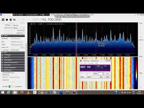
MPX Output plugin. Allows programs like RDS Spy to work with the audio output from SDR#
Aviation band 8.33 calculator. Automatically converts the current frequency input to an aviation one according to the standard 8.33 kHz channel spacing.
Frequency Lock. Simply locks the frequency change settings in SDR# to prevent accidental changes.
SDR Update Script. Not a plugin, but a script that automatically updates SDR# and installs most of Vasilli’s plugins all at once. To use this script, it must be placed in a subdirectory of the SDR# folder.
Here’s an example video of SDR# running the MPX plugin so that RDS Spy can be used.
The idea was to analyze the Doppler from the head echoes and and see if something useful can be extracted from them.
We detected a meteor from two distant locations and measured Doppler and Doppler slope at those locations. The we tried to find solutions to the meteor equation by brute force until we obtain a big number of them. Then we plotted those solutions in the sky and we see some of them pass near a known active radiant at the time of observation. Then, we checked the velocity of those solutions near the known radiant and found they are quite similar to the velocity of the known radiant, so we concluded probably they come from that radiant.
But they can come from everywhere else in the sky along the solution lines! There is not guarantee these meteors to be Geminids, although probabilities are high. Once all the possible radiants of a meteor are plotted into the sky, there is no way to know who of all them was the real one. Doppler only measurement from two different places is not enough to determine a meteor radiant. But don’t forget with some meteors, suspect to come from a known shower, the possible results includes the right radiant at the known meteor velocity for that radiant, so there seems to be some solid base fundamentals in this experiment.
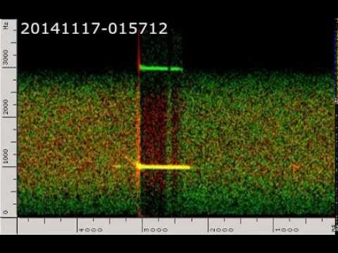
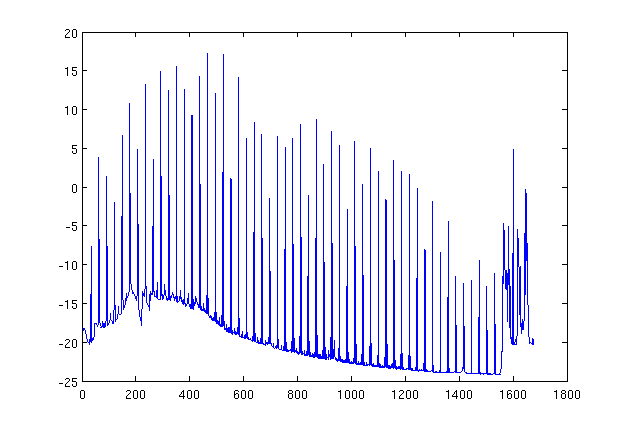
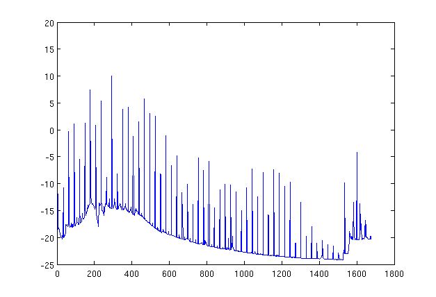
Initially they ran into a little trouble with their sound cards, as it turns out that sound cards don’t exactly sample at their exact specified sample rate. After properly resampling their sound files they were able to create a stereo wav file (one receiver on the left channel, one receiver on the right channel) which showed that the doppler signature was different in each location. The video below shows this wav file.
Double station meteor head echoes
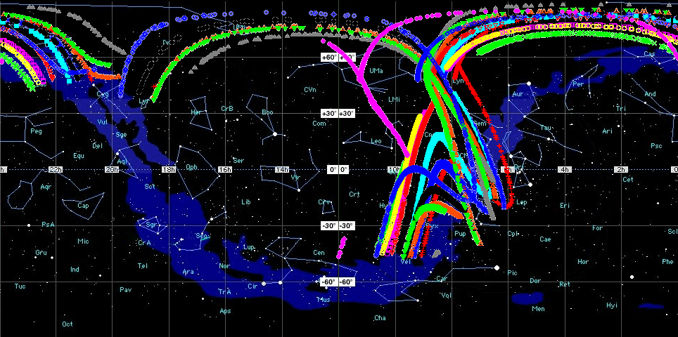
Using the information from their two separate recordings, they were able to do some doppler math, and determine a set of possible locations for the radiant of the meteors (it was not possible to pinpoint the exact location due to there being no inverse to the doppler equation). The radiant of a meteor shower is the point in the sky at which the meteors appear to be originating from. Although their solution couldn’t exactly pinpoint the location, some of the possible solutions from most meteors passed through the known radiant of the Geminids meteor shower. With more measurement locations the exact location could be pinpointed more accurately.
Possible solutions for the radiant of several meteors detected during the Geminids meteor shower.
Radio pirates often make use of the Fleetsatcom satellites to send and receive slow scan television (SSTV) pictures over a wide distance. Fleetsatcom is a satellite communications system used by the US Navy for radio communications. Since these satellites are simply radio repeaters with no authentication mechanisms, pirates soon discovered that they could take over the satellites for their own use.
Over on YouTube user LEGION ELMELENAS has uploaded a video showing his reception of some pirates transmitting a SSTV image at a Fleetsatcom frequency of 252 MHz. To receive the image he used a home made turnstile antenna, an RTL-SDR dongle, SDR# and the RX-SSTV decoder. The image appears to be a photo of a pirates son.
We previously posted more information about Fleetsatcom SSTV pirates in this post.
SSTV from Satcom satellites. RTL-SDR SDRSharp FLTSATCOM pirates
Over on YouTube user max30max31 (a.k.a IZ5RZR) has uploaded a video showing some of the steps in the tutorial as well as the real time result of decoding of the weather satellite image.
Back in September last year we posted a tutorial written by RTL-SDR.com reader Happysat which showed how to receive and decode high resolution Meteor-M2 LRPT satellite images. The tutorial required several offline manual processing steps to be performed and therefore could not decode the image in real time.
At the same time Vasili has also released another plugin called DDE Tracker which allows a satellite tracking program such as Orbitron to interface with and control SDR#. The plugin can be downloaded on the same page as the QPSK plugin. This is similar to the already existing DDE plugins, but now also comes with a scheduler which allows users to automatically schedule recordings of Meteor-M2 and NOAA satellite passings.
NOTE:Meteor M1 has come alive again, so the frequency of Meteor M2 was changed from 137.1 MHz to 137.9 MHz. Meteor M1 is now at 137.1 MHz and can be received using the same steps as in this tutorial, though please note that images from Meteor M1 are not perfect since the satellite is tumbling. Meteor M1 is gone again.
Tutorial
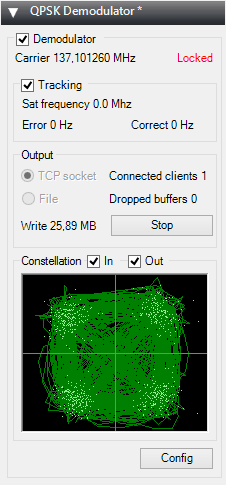
To help users get set up with this new method, Happysat has again come forth with another tutorial which can be downloaded here (.pdf) (.docx) (.txt w/ images in .rar). At first glance the tutorial may seem more complicated than the old method, but in the end it is a much faster and more efficient way at decoding LRPT images. The basic steps involve setting up Orbitron and the DDE plugin to automatically track the Meteor-M2 LRPT satellite and signal, and then setting up the QPSK plugin and the new version of Lrptdecoder (if that link is down, try this mirror) to talk to one another in real time via a local TCP connection.
Real time decoding of Meteor-M2 with two new SDR# Plugins.QPSK Demodulator SDR# PluginDDE Orbitron Interface SDR# Plugin.
AMIGOS
One more Meteor-M2 related thing to look forward to in the future is the AMIGOS project which stands for Amateur Meteor Images Global Observation System. This will be a system where users around the world can contribute LRPT images through the internet to create a worldwide LRPT receiver. Oleg of LrptDecoder writes:
There is an idea to merge LRPT receive amateur radio stations in a network through the Internet and create a super LRPT receiver.
I see the benefit of professionals from the control center in the operational monitoring of the condition of the equipment MSU-MR, and for fans of the fullest reception of images from Meteor-M.
All is in testing phase and need some setup for the servers, data is beeing shared thru a VPN connection to a central server which will have a continous flow of images from all over the world.
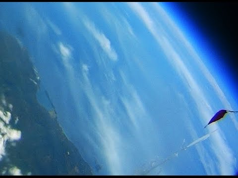
If you don't understand what all this is about: The Meteor-M N2 is a polar orbiting Russian weather satellite that was launched on July 8, 2014. Its main missions are weather forecasting, climate change monitoring, sea water monitoring/forecasting and space weather analysis/prediction.
The satellite is currently active with a Low Resolution Picture Transmission (LRPT) signal which broadcasts live weather satellite images, similar to the APT images produced by the NOAA satellites. LRPT images are however much better as they are transmitted as a digital signal with an image resolution 12 times greater than the aging analog NOAA APT signals. Some example Meteor weather images can be found on this page and the satellite can be tracked in Orbitron or online.
A software defined radio such as the low cost RTL-SDR, or the higher end Airspy and Funcube dongles can be used to receive these signals.
An Example LRPT Image Received with an RTL-SDR from the Meteor-2 M2.
Updates
The DDE plugin can also be used for tracking NOAA satellites. Some people have been having trouble with set up. Happysat writes a solution:
Over on YouTube user kpappa has uploaded a video showing his reception of the J43VHF radio amateur stratosphere balloon with an RTL-SDR dongle and discone antenna. On the 10th of May radio amateurs in Greece launched a high altitude balloon. The balloon carried a transceiver payload which allowed amateurs to talk to each other via the balloon at a frequency of 144.200 MHz. The video shows good reception of the balloon and also shows it’s tracking via APRS.fi.
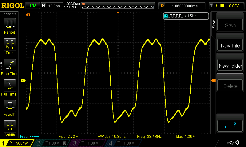
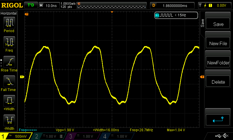
Now in order to reduce the number of spurious signals produced at multiples of 28.8 MHz by the external local oscillator, Milan has added a simple low pass filter to the oscillator output. He used a 3-pole Butterworth filter with a 30 MHz cut off point. This filter acts to the convert the Si535A’s square wave output into a sine wave, which should help reduce the number of spurious signals produced.
Square wave before filtering.Closer to a sine wave after filtering.
Milan tested his filtering by creating a wideband comparison sweep with rtl_power. With the low pass oscillator inserted, the spurious signals were clearly reduced a significant amount. Then by reducing the drive level from 8mA to 2mA, the spurious signals were reduced even more. By using a filter with more poles it’s possible that the spurious signals could be reduced even further.
Spurious signals with no low pass filter added.Spurious signals are reduced after adding the low pass filter.
With the recent release of ADSBSpy, an ADS-B decoder for the Airspy software defined radio, many people have been wondering how much better the Airspy is compared to the low cost RTL-SDR dongle at ADS-B reception. Over on his blog, Anthony Stirk has performed a test comparing an E4000 RTL-SDR with the Airspy.
In his test Anthony uses an A3 ADS-B antenna from Jetvision.de, and a HABAMP which is an LNA plus 1090 MHZ SAW filter. To create a fair test he used an antenna splitter and measured the reception of both dongles at the same time. He ran one instance of ADSB# for the E4000 RTL-SDR, and one instance of ADSBSpy for the Airspy over 24 hours and recorded the results.
Airspy vs E4000 RTL-SDR
The results showed that the Airspy had approximately 50 km more range compared to the E4000 in some areas. More interestingly the stats showed that the Airspy received approximately 7 million more ADS-B messages compared to the RTL-SDR.
While there is no doubt the Airspy will perform better, one thing to note about this test is that it used an E4000 RTL-SDR which is widely considered to have inferior performance at the 1090 MHz ADS-B frequency when compared to the R820T/2 dongles.