Combining the bandwidth of two RTL-SDR dongles in GNU Radio
The maximum usable and stable bandwidth of an RTL-SDR is about 2.4 MHz. In order to get larger bandwidths it is possible to combine two or more dongles, although doing so comes with a big limitation – since the clocks and signal phases between separate dongles would not be synchronised, it would be impossible to decode a wideband signal this way. However, combining dongles for larger bandwidths is still useful for visualizing the spectrum through an FFT plot, or perhaps for decoding various separate narrowband signals. Although creating a wide band FFT plot with multiple dongles is fairly simple, we haven’t seen much software do this before.
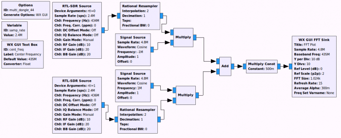
However now RTL-SDR.com reader Oliver wrote in to show us the GNU Radio script he’s been using to combine the bandwidths of two RTL-SDR dongles together to get a 4.4 MHz FFT display. The script can be used to get a combined 4.4 MHz spectrum visualization without a center dip from roll off, or a 4.8 MHz spectrum with rolloff. Oliver writes:
I simply took two RTL-SDR dongles at their max. band width of 2.4 MHz, resampled the signals to 4.8 MHz, then shifted the first signal down by 1MHz, the other one 1 MHz up, added them together, divided the combined signal by 2 and finally feed it into a FFT plot.
At first, I tried shifting the signals by 1.2 MHz to get full 4.8 MHz, but I realized, that I had a notch in the center, so I reduced the frequency shift until I had no notch anymore.


you don’t even need an ‘external’ clock. there was one defcon talk, where someone used the xtal output to sync 2 other dongles.
@fusionimage: how is that not an external clock relative to those other dongles?
would feeding an external clock source into the dongles allow synchronised reception and decoding?
You’d like it to…. but, synchronizing the clock to signal…no such thing- ultimately we are saying ,”at this moment, it is X(X being the clock reference to sync to )”. Problem here is accuracy/ consistency/ the initial mating of signal to partnered clock are arbitrary at best….. based on random choice or personal whim, rather than any reason or system. Sure, maybe here and there the matching of signal with clock work out- more often, you’d just be throwing out a value and seeing what sticks… that is no way of providing accurate sata, nor data that can be further worked with.
You’ll find yourself “tweaking”, adjusting…manipulating your signal- so that you can “hit that sweet spot” in order to further process it- a major headache if not just a long winding path of trying to learn some abstract maggical way of producing the desired outcome- this is no way of doing things.
Now enter a device with internal or integrated ‘external’ clock and signal ABC at X is ABC at X. Where calibrated appropriately, sibling device(s) see signal ABC at? That is right, at X- so now, yo can see how this is – it is, what it is- no guessing, no massaging data, no willy nilly/ mickey mouse operation of data analysis/ processing. Accuracy and information that can be further processed with ease(certain ease ) – confidence of results.