An Overview of the Elektor SDR Hands-on Arduino Shield Kit

Over on YouTube, Elektor have uploaded an overview of their Elektor SDR Hands-on kit. The €49.46 kit is an Arduino shield, that turns an Arduino microcontroller board into a 150 kHz to 30 MHz capable SDR receiver. It is based on the G8JCFSDR, which is an RF front end downconverter that allows a PC soundcard to be used as an SDR analog to digital converter.

To compliment the SDR is a book that goes over introductory topics such as shortwave reception, explains signal to noise ratio and interference, different types of antennas, software, digital modes, SDR measurements, receiving and finally WSPR and QRP transmissions. Overall this looks like a good kit for learning about the technical basics of SDRs.

An Overview of the Elektor SDR Hands-on Kit

Using HackRFs to Locate a UAV Transmitter via Signal Strength Analysis

During the 2019 IEEE International Symposium on Broadband Multimedia Systems and Broadcasting conference, authors Xuemei Huang, Kun Yan, Hsiao-Chun Wu and Yiyan Wu presented a research paper titled "Unmanned Aerial Vehicle Hub Detection Using Software-Defined Radio". In their work they describe how they were able to use three HackRFs to determine the location of a UAV drone transmitter. The method they use is fairly simple as it makes use of path loss propagation models to determine an estimated distance from each HackRF, so prior knowledge of the transmitter properties is still required.

The applications of unmanned aerial vehicles (UAVs) have increased dramatically in the past decade. Meanwhile, close-range UAV detection has been intriguing by many researchers for its great importance in privacy, security, and safety control. Positioning of the UAV controller (hub) is quite challenging but still difficult. In order to combat this emerging problem for public interest, we propose to utilize a software-defined radio (SDR) platform, namely HackRF One, to enable the UAV hub detection and localization. The SDR receiver can acquire the UAV source signals. The theoretical path-loss propagation model is adopted to predict the signal strength attenuation. Thus, the UAV hub location can be estimated using the modified multilateration approach by only three or more SDR receivers.

Unmanned Aerial Vehicle Hub Detection Using Software-Defined Radio

A Neat HF SDR Receiver made from an Audio Reverb Chip

Over on his blog, Ray Ring has posted about his neat little "Mini SDRadio" made from an Si5351 clock generator and a FV-1 reverb audio processor chip.

The Spin Semiconductor FV-1 is a digital reverb chip designed for creating custom audio effects in products. As it is a digital chip it makes use of an ADC and DAC, with the audio effects DSP placed in the middle of the chain. However, by using custom code Ray was able to convert the ADC into an SDR by creating custom AM/FM and LSB demodulators on the programmable DSP instead of the audio effects.

His post contains the full schematics, code and PCB files required to recreate his work if desired.

[Also covered on Hackaday]

Demo of mini SDR receiving VOLMET Station

Shazam Style Automatic Signal Identification via the Sigidwiki Database

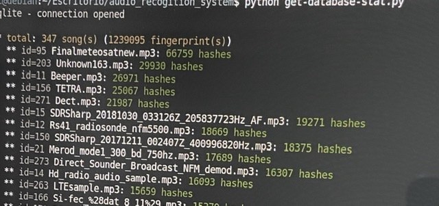
Thank you to José Carlos Rueda for submitting news about his work on converting a "Shazam"-like Python program made originally for song identification into a program that can be used to automatically identify radio signals based on their demodulated audio sounds. Shazam is a popular app for smartphones that can pull up the name of any song playing within seconds via the microphone. It works by using audio fingerprinting algorithms and a database of stored song fingerprints.

Using similar algorithm to Shazam, programmer Joseph Balikuddembe created an open source program called "audio_recogition_system" [sic] which was designed for creating your own audio fingerprint databases out of any mp3 files.

José then had the clever idea to take the database of signal sounds from sigidwiki.com, and create an identification database of signal sounds for audio_recogition_system. He writes that from his database the program can now identify up to 350 known signals from the sigidwiki database. His page contains the installation instructions and a link to download his premade database. The software can identify via audio that is input from the PC microphone/virtual audio cable or from a file.

Fingerprinted Audio Samples of Radio Signals

Cheap and Easy Hydrogen Line Radio Astronomy with an RTL-SDR, WiFi Parabolic Grid Dish, LNA and SDRSharp

We've recently been testing methods to help budding amateur radio astronomers get into the hobby cheaply and easily. We have found that a low cost 2.4 GHz 100 cm x 60 cm parabolic WiFi grid antenna, combined with an RTL-SDR and LNA is sufficient to detect the hydrogen line peak and doppler shifts of the galactic plane. This means that you can create backyard hydrogen line radio telescope for less than US$200, with no complicated construction required.

If you don't know what the hydrogen line is, we'll explain it here. Hydrogen atoms randomly emit photons at a wavelength of 21cm (1420.4058 MHz). Normally a single hydrogen atom will only very rarely emit a photon, but the galaxy and even empty space is filled with many hydrogen atoms, so the average effect is an observable RF power spike at ~1420.4058 MHz. By pointing a radio telescope at the night sky and averaging the RF power over time, a power spike indicating the hydrogen line can be observed in a frequency spectrum plot. This can be used for some interesting experiments, for example you could measure the size and shape of our galaxy. Thicker areas of the galaxy will have more hydrogen and thus a larger spike, whereas the spike will be significantly smaller when pointing at empty space. You can also measure the rotational speed of our galaxy by noting the frequency doppler shift.

The 2.4 GHz parabolic WiFi grid dishes can be found for a cheap at US$49.99 on eBay and for around US$75 on Amazon. Outside of the USA they are typically carried by local wireless communications stores or the local eBay/Amazon equivalent. If you're buying one, be sure to get the 2.4 GHz version and NOT the 5 GHz version. If you can find 1.9 GHz parabolic grid dish, then this is also a good choice. Although we haven't tested it, this larger 2.4 GHz grid dish would probably also work and give slightly better results. WiFi grid antennas have been commonly used for GOES and GK-2A geosynchronous weather satellite reception at 2.4 GHz with RTL-SDRs as well and we have a tutorial on that available on our previous post.

These dishes are linearly polarized but that is okay as hydrogen line emissions are randomly polarized. Ideally we would have a dual polarization (NOT circular polarized) feed, but linear appears to be enough and is much simpler. In addition, the 2.4 GHz feed is obviously not designed for 1420 MHz, but just like with GOES at 1.7 GHz the SWR is low enough that it still works.

The animation below shows a hydrogen line "drift" scan performed with the 2.4 GHz WiFi dish, an RTL-SDR Blog V3 and a NooElec SAWBird H1 LNA. The scan is performed over one day, and we simply let the rotation of the earth allow the Milky Way to drift over the antenna. The Stellarium software on the left shows the movement of the Milky Way/galactic plane over the course of a day for our location. The dish antenna points straight up into the sky, and we have set Stellarium to look straight up too, so Stellarium sees exactly what our dish antenna is seeing.


You can clearly see that there is a lump in the radio spectrum at around 1420.40 MHz that grows when parts of the Milky Way pass over the antenna. This lump is the hydrogen line being detected. As our Milky Way galaxy is filled with significantly more hydrogen than empty space, we see a larger lump when the antenna points at the Milky Way, and only a very small lump when it points away.

It's important to ignore the very narrowband spikes in the spectrum. These narrowband spikes are simply radio interference from electronics from neighbors - probably TVs or monitors as we note that most of the interference occurs during the day. There is also a large constant spike which appears to be an artifact of the LNA. The LNA we used has a 1420 MHz filter built in, but LCD TVs and other electronics in today's suburban environment spew noise all across the spectrum, even at 1420 MHz.

You can also note that the hydrogen line peak is moving around in frequency as different parts of the galaxy pass overhead. This indicates the doppler shift of the part of the galaxy being observed. Because the arms of the galaxy and the hydrogen in it is rotating at significant speeds, the frequency is doppler shifted relative to us.

Using the power and doppler shift data of the hydrogen line is how astronomers first determined the properties of our galaxy like shape, size and rotational speed. If we continued to scan the sky over a few months, we could eventually build up a full map of our galaxy, like what CCERA have done as explained in this previous post.

Continue reading

A FM Radio Passive Radar System from Two RTL-SDR Dongles

Over on his blog, Max Manning has posted about his senior year design project which was an RTL-SDR based passive radar system that he created with his project partner Derek Capone. Max's writeup explains what passive radar is, and how the theory works in a very easy to understand way, utilizing graphs and short animations to help with the understanding. The rest of the post then goes into some deeper math, which is also fully explained.

Passive Radar works by using already existing powerful transmitters such as those for TV/FM. A receiver listens for these signals being reflected off of objects like aircraft and vehicles, and compares the reflection with a signal received directly from the transmitter. From this information a speed/range graph of detected objects can be calculated

For hardware, the team used two RTL-SDR dongles with the local oscillators connected together. A standard dipole is used as the reference antenna, and a 5-element Yagi is used as the surveillance antenna.

Max's post is a great read for those trying to understand how to do passive radar with a KerberosSDR which is our 4x coherent input RTL-SDR unit available from the Othernet store or Hacker warehouse. Being a radio capable of coherency, it is useful for applications like passive radar and direction finding. 

Their code is all open source and available on GitHub. We note that their code should also work with KerberosSDR with only either zero to minor modifications required. However, for the KerberosSDR we also have our own passive radar code available which might be a little easier to setup via the GUI.

Passive Radar with Two RTL-SDR dongles sharing a single clock.

How to Not Break Your SDR + Other Articles from oneSDR

A new software defined radio blog called onesdr.com has recently posted a useful article for radio world newbies called "How Not to Break your Software-defined Radio Hardware". The article goes over a few important precautions like avoiding input power which is too high from transmitters and LNAs, avoiding DC input, and avoiding ESD.

They've also uploaded a few other articles that may be useful like "What is a Bias Tee?", "FM Notch Filters – why you need one with most SDRs", "What to look for when buying a Software-Defined Radio (SDR)", "Should I place a Low Noise Amplifier Before or After a Filter?", "The Best Software-Defined Radios (SDRs) for 2020" as well as several more.

Hackaday Tutorial: A Crash Course in RF Modulation – ASK, FSK and LoRa Explained Simply

Hackaday writer Danie Conradie has recently posted a new tutorial explaining the difference between some common RF modulation choices. To do this he uses various RF hardware modules, and an RTL-SDR Blog V3 unit to view the spectrum of each modulation type. In the post he compares Amplitude Shift Keying (ASK), Frequency Shift Keying (FSK), and LoRa. He also explains the differences between ASK and OOK modulation, and FSK and GFSK modulation.

The key takeaways are that ASK modulation is simple, but prone to interference. FSK is less prone to interference, but requires more bandwidth. LoRa is good for receiver sensitivity and interference immunity, but comes at the expense of bandwidth efficiency. In addition LoRa modulation is patented, resulting in higher hardware costs.

Comparing the spectrum of a pure FSK signal, versus a Gaussian FSK signal.