The Arecibo Radio Telescope has collapsed. Once the largest single dish radio telescope in the world at 305m, Arecibo was mostly used for radio astronomy research. However, the dish was made famous in 1974 for deliberating beaming a message into space as part of a search for extraterrestrial intelligence (SETI) experiment. It also played a part in popular culture, being a part of several famous films such as Golden Eye and Contact.
As part of it's goodbye we thought we'd highlight a few old posts where Arecibo was used together with SDRs for some interesting applications.
The project required finding and researching the original spacecraft documentation, and implementing the modulators and demodulators in GNU Radio. Whilst being successful in communicating with the satellite, ultimately the project failed due to the satellite's nitrogen tanks which had long leaked empty. But the fact that they were even able to find and communicate with the spacecraft using Arecibo was a major achievement. If you're interested in that project, Balint's 2015 talk on YouTube is an interesting watch.
Later in 2017 we saw how Arecibo was used for an Ionospheric heating experiment which involved transmitting 600kW of net power into the Ionosphere. This resulted in SDR users around the world being able to receive the signal. Other posts involve u/moslers Reddit post where he toured Arecibo and showed how they used a familiar program, HDSDR, as part of their monitoring suite.
So goodbye to Arecibo. However, we can look forward to the 500 meter Chinese FAST (Five-hundred-meter Aperture Spherical Radio Telescope) giving us new opportunities for single dish radio observations in the future.
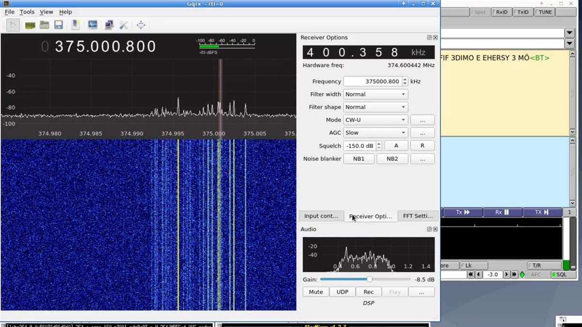
The answer is yes, there is some RF leakage, however unlike the Pi 4 the speed at which the leakage can be modulated is much slower, and also the signal strength is much lower. Despite the slow modulation speed, Jacek was still able to transmit data by using QRSS CW, which is essentially just very slow morse code. Using this idea he was able to transmit, and receive the CW signal with an RTL-SDR over a distance of 3 meters at 375 MHz, 625 MHz and 250 MHz. The signal strength is nothing like the Pi 4's Ethernet RF leakage which can be received strongly from over 50 meters away however.
Etherify: Transmitting QRSS CW via Ethernet RF leakage from PC to PC
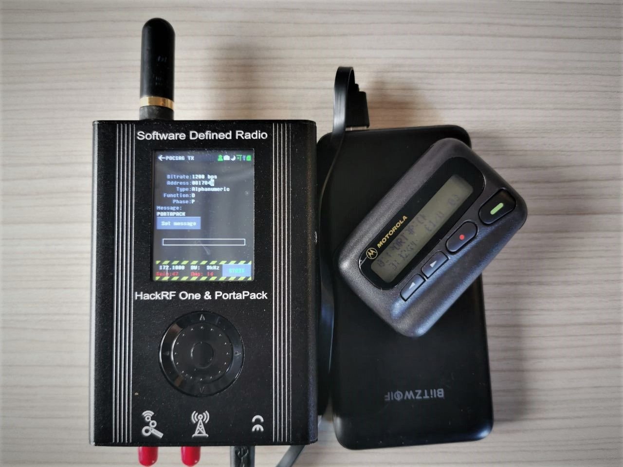
The Portapack is an add on for the popular HackRF SDR which allows the HackRF to be used portably without a PC. Recently the cost of this hardware duo has come down to below US$150 due to low cost Chinese clones now being available on the market. Generally the clones are of good quality too.
Once you have the hardware it is possible to install third party custom firmware such as "Mayhem" on the Portapack which enables many features such as the ability to receive and transmit various different types of RF protocols. Back in 2018 we did a review of Mayhems predecessor which was known as the "Havok" firmware. More recently Tech Minds did a video overview of Mayhem.
Now over on his blog A. Petazzoni has started a new blog series which aims to introduce the basics of the Mayhem firmware, including installation and some hands on testing with RF spoofing, denial-of-service (DoS) and replay attacks. Currently only his first post is out, and in the post he show how to install Mayhem onto the Portapack, then goes on to briefly overview some applications such as RF replay attacks, replicating wireless remote controls, receiving and transmitting POCSAG, receiving and transmitting ADS-B, and creating a jammer.
Obviously a lot of what you can do with a Portapack and the Mayhem firmware is extremely illegal and very dangerous, so please do be careful with what and where you transmit especially if you are new to RF hobby. These signals should remain in your test area only, and not leak out into the wider environment.
Earlier this year SDRplay updated their SDRuno software to have plugin functionality. This allows third party programmers to implement their own decoders and software which interfaces with SDRuno directly. Recently we've seen some new plugins become public, and in one of their recent blog posts, SDRplay highlights a few new ones.
SDRplay writes the following about three demonstration videos:
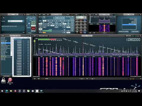
The first shows the latest version of FRAN – a FRequency ANnotation programme, developed by Eric Cottrell – it can read SWSKEDS or .s1b memory bank files and display the active stations from the files on the main spectrum window. This is an example of a Community Plugin
Quick Look at the FRAN Plugin (VID558)
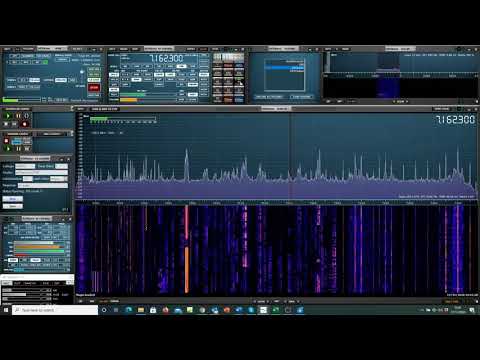
FRAN complements the DX Cluster demo plugin provided by SDRplay. This programme displays DX cluster callsigns on the SDRuno spectrum display. A DX cluster is a network of computers, each running a software package dedicated to gathering, and disseminating, information on amateur radio DX activities. With this plugin you can overlay the DX cluster callsigns as they pop up. There’s a choice of how long you let them display and you can control the way in which they appear. Here we show it successfully tuning in to a US station flagged by the cluster. (The receiver was in the UK):
Quick Look at the DXcluster Plugin (VID560)
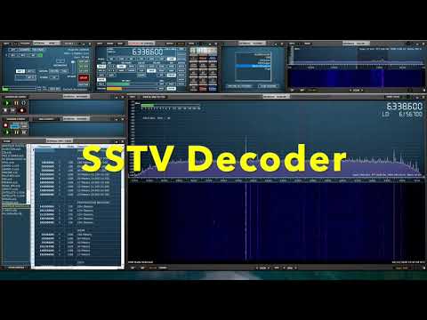
Finally there’s this new video showing the new plugin for interfacing the software suite from Black Cat Systems to SDRuno enabling DXToolbox, HF WEFAX and Slow Scan TV decodes:
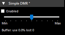
Simple DMR decoder. No external dependencies, no settings, uses SDR # audio path. Designed for listening to unencrypted DMR channels. The voice from both slots is mixed into one channel.
To install the plugin simply copy the dll's from the zip file into the SDR# folder, then copy the line from the magline.txt text file into the plugins.xml file which can be opened with any text editor.
We've posted about Job Geheniau's RTL-SDR radio telescope a few times in the past [1] [2] [3], and every time his results improve. This time is no exception as he's created his highest resolution radio image of the Milky Way to date. We have uploaded his PDF file explaining the project here.
Job used the same hardware as his previous measurements, a 1.5 meter dish, with 2x LNA's, a band pass filter and an RTL-SDR. Over 72 days he used the drift scan technique to collect data in 5 degree increments. The result is a map of our Milky Way galaxy at the neutral Hydrogen frequency of 1420.405 MHz.
JRT - Northern sky Hydrogen Line Survey with RTL-SDR
This image is quite comparable to an image shown in a previous post which was created by Marcus Leech from CCERA who used a 1.8m dish and Airspy.
If you're interested in exploring our Galaxy with an RTL-SDR via Hydrogen Line reception, we have a simple tutorial available here. The ideas presented in the tutorial could be adapted to create an image similar to the above, although with lower resolution.
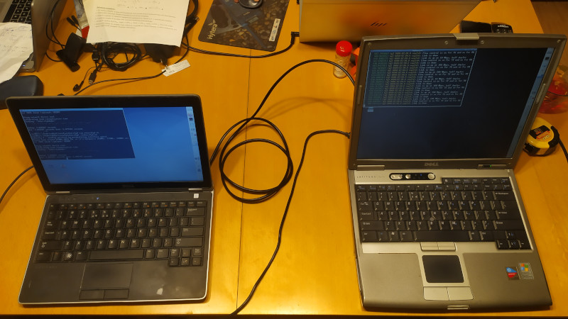
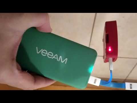
Not too long ago we posted about Jacek Lipkowski (SQ5BPF)'s project called "Etherify" which seeks to use unintentional RF radiation from Ethernet hardware/cables to transmit arbitrary signals such as morse code and FSK. During his earlier experiments he noted how he felt that the Raspberry Pi 4 had an unusually strong radiated Ethernet signal. In his recent post Jacek investigates this further.
Indeed his new tests seem to confirm that the Pi 4 has excessive RF leakage from the Ethernet hardware. His latest results have shown that he was able to receive the Ethernet leakage strongly from 50 meters away without any cable connected to the Ethernet port to act as a radiator. Jacek's post contains a number of demonstration videos such as the one below.
He admits that his particular Pi 4 unit might be unique in this regard. If anyone else tests this and can confirm excessive leakage, please let us know in the comments.
Ethernet RF leakage received strongly from 50m away without any antenna on the Pi 4
John from JR Magnetics has written in and wanted to share his Kickstarter for a US$50 ultra wide band antenna that he has designed. The size is a just little bit bigger than two credit cards and the advertised coverage is from 750 MHz up to 6 GHz with a VSWR of less than 2.0.
John's Kickstarter text reads below:
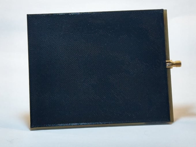
Flat Ultra Wide Band Antenna Suitable for SDR
About
I was never satisfied with the commercially available wide band antennas. They were all too large or did not have suitable VSWR over the frequency range generally required by SDRs. I read many research papers and ultimately made a omni-directional ultra wide band antenna, but it was too expensive for most people. Details regarding that antenna can be found at https://www.rtl-sdr.com/constructing-a-3d-printed-wideband-900-mhz-to-11-ghz-antenna/
However, a bi-directional antenna was good enough for most people, so I have made a flat one. The antenna I ended up with is 5 inches by 4 inches and about 3 mm thick with an SMA connector. It is quite definitely not a square patch antenna, which usually has a narrow bandwidth.
This antenna has a VSWR measured to be under 2.00 from around 750 MHz to over 3 GHz. It simulates to have a VSWR under 2.00 out to over 6 Ghz. This is enough for most of the available SDRs. It works very well with WiFi, Bluetooth, Zigbee and other systems within the bandwidth.
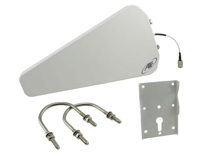
Typical Directional Log Antenna
Existing Antennas
The log antenna, Figure 2, has a wide bandwidth, but it is specified as having ranges, because the VSWR rises over 2.00 several times over that range. The antenna measure sover 40 centimeters long, which is problem for me in a laboratory setting. It is too large to fit anywhere and wants to be permanently fixed to a pole or something like that.
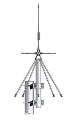
The other antenna I have is a discone type device, Figure 3. It is huge. There is not practical for it to fit on a lab bench around various RF devices. It is measures around 28 centimeters at its base. It needs to be elevated above any ground planes, which complicates a laboratory environment with metal bench tops. I have it sitting on a shelf above the computer monitors on the opposite side of the room away from the lab bench. This does not work well when I am trying to deal with wireless devices connected to USB hubs on the bench with short range features.
Discone Type Wide Band Antenna
Figure 4 shows the Flat Antenna next to the Log Antenna for a size comparison that illustrates just how much space saving there is with this new device. This is no small feat. This Flat Antenna is useful around all manner of RF devices on the bench without causing space issues, getting in the way of instruments and couples well with all of the wireless devices I am using. It is small enough with a convenient shape for moving it around and keeping it above a metal bench top. It only needs to be a few centimeters above any ground planes when perpendicular, not horizonal.
Due to its size and shape, near field problems have not been a problem, as with the other antennas. The antenna is quite directional, which is not much of a problem, since the RF bounces around all over the place. A Faraday shield is the only way to keep this device from picking out everything in the vicinity. The neighbors IoT devices create mountains of RF clutter. This antenna picks up all of it. If you only want restricted bandwidths, band pass and reject filters can be used. The load impedance is 50 Ohms across the band making an excellent match for all of the filters I have here.
Our Flat Antenna Size Comparison with the Log Antenna
Specifications
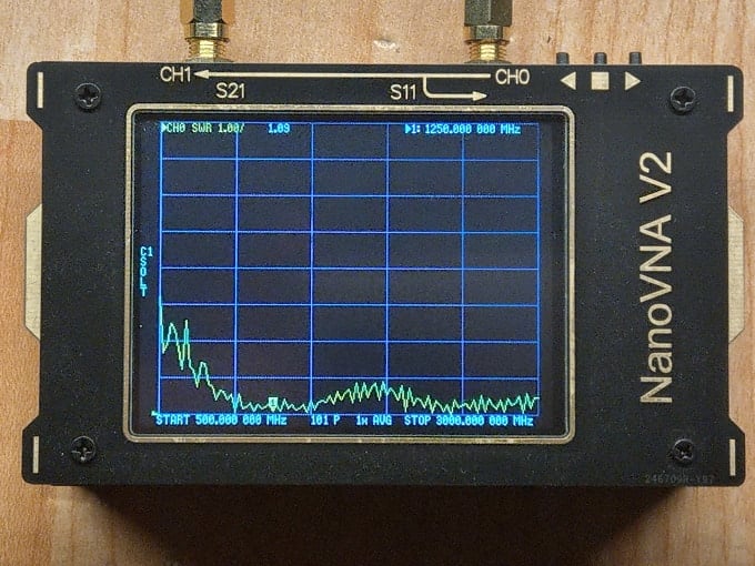
Figure 5 shows the VSWR as measured by the NanoVNA Version 2. It only goes out to 3 Ghz. The device must be calibrated before use, or you will get extraneous results. I am told the VSWR never goes above 2.00 until after 6 GHz. This is a remarkable antenna. I never found anything comparable to it on the Internet.
It can be used for all wireless and SDR applications normally within the 750 MHz to 6 GHz bandwidth. This is not guess work or speculation. The network analyzer shows the response clearly.
The antenna is 5 inches long by 4 inches wide by roughly 3 mm thick, not counting the SMA connector.
VSWR of Our Flat Antenna
What You Get
You get one (1) antenna, as shown in Figure 1, for each US$50. You cannot do this yourself for that price. Your time alone is worth more than that after you do the calculations, simulations and prototyping. You also would have to deal with fab shops to get this done correctly, which is not always convenient for many people.
In other words, this is a remarkable Ultra Wide Band Antenna at a remarkable price.
Engineering
This has already been done. I have a Masters Degree in RF Engineering. I also have all of the simulation tools that are not available to most people, with the exception of some university students.
Manufacturing
I have sources that I use all the time. I just put this one into the queue. We also have a minimum order, which is why we Crowd Fund this operation.
Timeline
Once in the queue, it takes about two (2) weeks. After that, we are only concerned with delivery time. We intend to use ordinaty Postal Service mail, to keep the cost down, so time of delivery may vary depending upon the destination.
Risks and challenges
We already have laboratory results, so there is nothing to risk in performance. The only other thing that could be troublesome is the lead time by the vendor that manufactures the main component or any delays caused by the Postal Service.
UPDATE 16 Dec 2020:John has provided us with this document that addresses a few questions people had about the antenna.