His initial idea was to create a flexible and open portable SDR device, however keeping the device open and built for general use meant increased complexity which quickly slowed his progress. Instead [Nathan] decided to focus on just ADS-B for his portable device as living near an airport he’d been interested in aircraft tracking since his first SDR arrived.
The device consists of a Raspberry Zero, RTL-SDR, 3.5″ IPS LCD and a battery pack for portability. For software he uses dump1090 with some custom code for the map plotting. Together with a 3D printed case and some buttons, the result is a very professional looking portable aircraft tracking device.
Hopefully Nathan will continue updating his project page so that others may replicate it on their own.
Raspberry Pi Zero and RTL-SDR Portable ADS-B Receiver
Last year in December we posted about Matt's element14 sponsored video which showed us how to create a portable briefcase contained NOAA satellite received based on a Raspberry Pi and RTL-SDR dongle. The build consisted of a heavy duty briefcase, modified ATX PSU and stripped down LCD monitor panel. This build resulted in a rugged and portable receiver. The full series of videos demonstrating the briefcase, ATX PSU conversion, LCD teardown, and NOAA satellite receiver demo can be found on his YouTube Playlist.
In his latest video Matt goes over the software installation procedure for creating an automated NOAA weather satellite receiver on the Raspberry Pi. He uses gpredict for predicting the satellite passes, and the Raspberry Pi version of WXtoImg for decoding the images. The rest of the video shows how to set up the software for your particular location, and how to set up decoding automation.
How To Set Up a Raspberry Pi as a NOAA Satellite Receiver with RTL-SDR
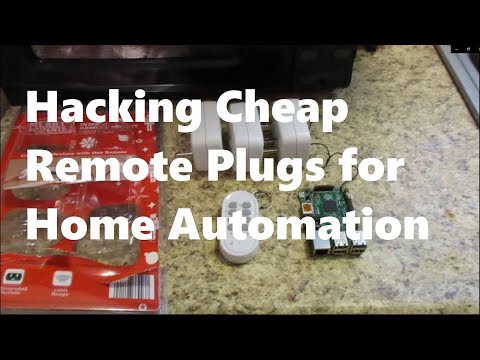
Over on his YouTube channel ModernHam has created a video showing him using an RTL-SDR and Raspberry Pi with RPiTX to record and replay the signal generated by the remote of a wireless power plug. A wireless power plug allows you to turn an AC wall outlet on/of remotely via a remote control. Controlling them with a Raspberry Pi can be a simple way to add home automation. One example ModernHam gives is that he hopes to use RPiTX and the wireless power plugs to create a smart coffee pot that will automatically turn on at 7 am, and turn off at 9 am.
In the past we have created a similar tutorial here, but new updates to RPiTX now make this process much easier and more reliable and ModernHam's video shows the new procedure. The new process is simply to look up the FCC frequency of the remote control transmitter, record an IQ file of the transmissions for the ON and OFF buttons, and then use the RPiTX sendiq command to replay the signal. You can then use simple Linux shell scripts to create automation.
Replay Attack with Remote Plugs for Home Automation with the Raspberry PI
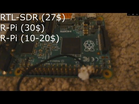
Over on YouTube user ModernHam has uploaded a video showing how to perform a replay attack on a car key fob using a Raspberry Pi running RPiTX and an RTL-SDR. A replay attack consists of recording an RF signal, and then simply replaying it again with a transmit capable radio. RPiTX is a program that can turn a Raspberry Pi into a general purpose RF transmitter without the need for any additional hardware.
The process is to record a raw IQ file with the RTL-SDR, and then use RPiTX V2's "sendiq" command to transmit the exact same signal again whenever you want. With this set up he's able to unlock his 2006 Toyota Camry at will with RPiTX.
We note that this sort of simple replay attack will only work on older model cars that do not use rolling code security. Rolling code security works by ensuring that an unlock transmission can only be utilized once, rendering replays ineffective. However, modern rolling code security systems are still susceptible to 'rolljam' style attacks.
In the video below ModernHam goes through the process from the beginning, showing how to install the RTL-SDR drivers and RPiTX. Near the end of the video he shows the replay attack in action.
Unlock Cars with a Raspberry Pi And SDR - Replay attack
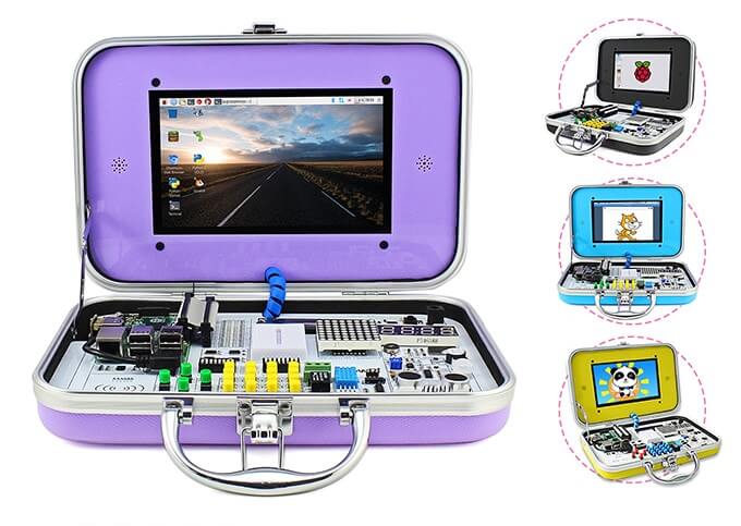
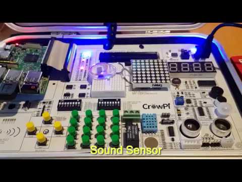
CrowPi is a Raspberry Pi all-in-one experimenters kit that is currently crowd funding on Kickstarter. The idea behind CrowPi is to combine a touchscreen, various sensors, actuators and interfaces into a clutter free kit mounted on a PCB in an easy to carry hard shell case. It's mostly intended to be used in STEM learning environments, however it could also be used for rapid prototyping of Raspberry Pi based ideas, or simply as a portable computer.
The CrowPi
The kit has 4 days left on Kickstarter and has already met its minimum goal. Pledging $1,169 HKD (~USD $150) gets you the basic kit which does not include a Raspberry Pi. Higher pledge levels (up to US$250) get you models that include a Raspberry Pi as well as extras such as a 5V power supplies, earphones, heatsinks, keyboards, game controllers etc. Shipping of the units is expected to commence in July.
Elecrow, the Shenzhen based company behind CrowPi kindly sent us a free kit for an honest review. While not directly related to RTL-SDR or RF, we thought that there might be several applications that might make the CrowPi kit useful for prototyping some simple low cost RF based ideas. For example:
Prototyping IoT based modules that use the RTL-SDR as a receiver. For example receiving a 433 MHz ISM signal and writing received information to the LCD/LED array or activating the relay.
Similarly, using FL2K-SDR or RPiTX to transmit a signal when a sensor is activated, or to transmit telemetry from that sensor (e.g. distance data from the ultrasonic sensor, humidity levels from the DH11 sensor, or light levels from the light sensor)
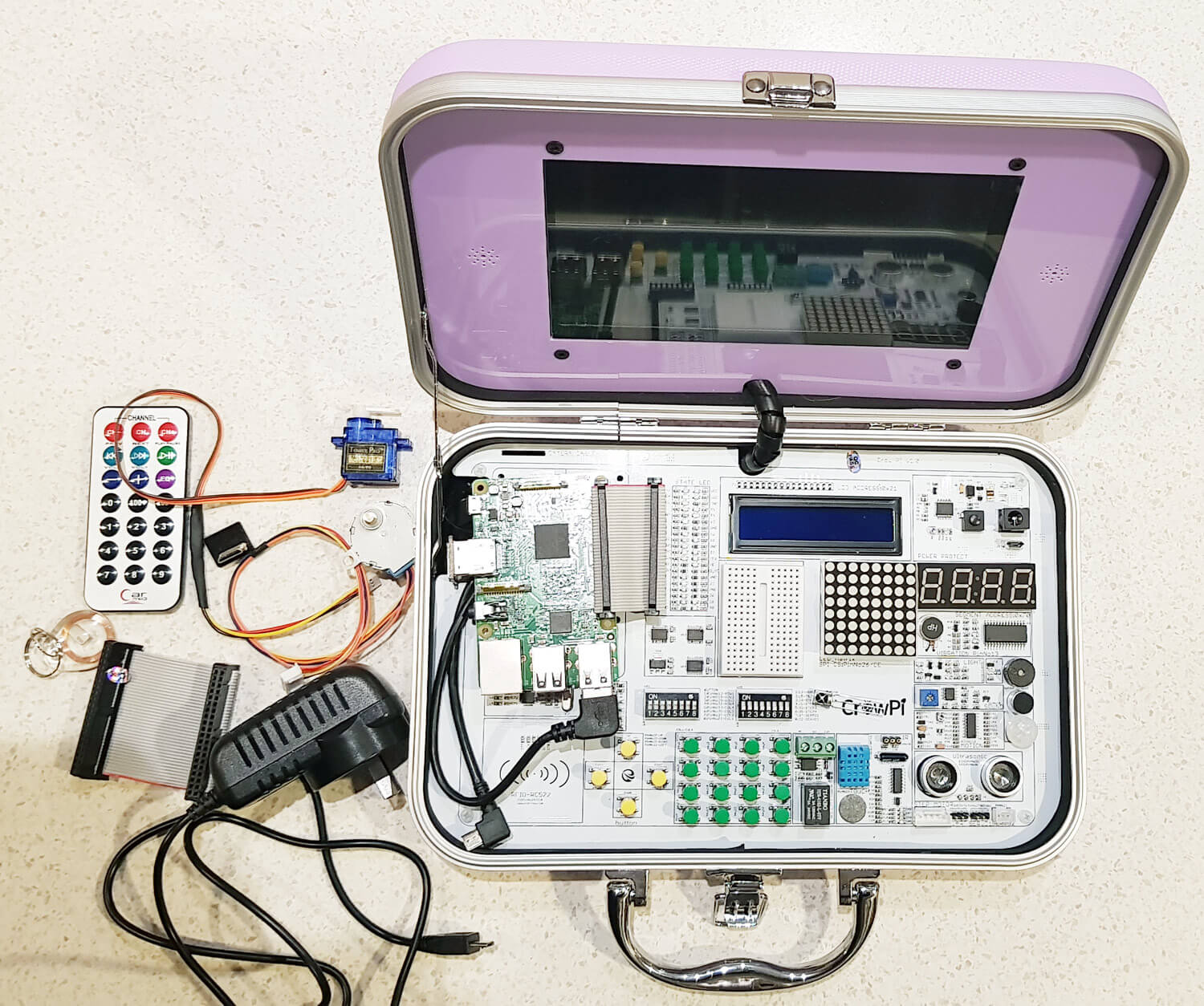
To get an idea of what's packed into the CrowPi, the kit includes the following modules:
Everything that came with our CrowPi Demo Kit (Except the Raspberry Pi)
1920 x 1080 Capable HDMI 7" Touch Screen
LCD Module
8x8 Matrix LED
Breadboard
4 character 7-seg LED
Vibration motor
Light Sensor
Buzzer
Sound Sensor
Motion Sensor
Ultrasonic Sensor
Servo Interface
Step Motor Interface
UART
Tilt Sensor
IR Sensor
Touch Sensor
DH11 Humidity Sensor
Relay
Matrix of buttons
RFID Module
With our kit we also received:
2x GPIO Flex Cables
1x Stepper Motor
1x Servo
1x Charger
1x IR diode
1x NFC Tag
1x Mini HDMI for the Raspberry Pi Zero
1x IR Remote control
Setup, Initial Testing and Thoughts
Setup: Setup was simple and consisted of downloading their customized Raspberry Pi image onto an SD card, connecting the Raspberry Pi to the HDMI, USB and GPIO pins, and then powering it up using the power jack on the CrowPi Board. A user manual is available for download.
Initial Testing: CrowPi provide a set of lessons that show how to use each of the modules on the board. All modules also have Python code examples that are ready to run as soon as you boot up. Immediately after booting up we were able to run their demo code which allowed us to test all the various sensors, print text to the LCD module, activate the 7-seg display, and actuate a servo and stepper motor.
The tutorials are easy to understand and provide a good basic rundown of the sensors. You will need to have some basic Python skills to understand the Python code however.
Thoughts: The CrowPi is built sturdy, and is definitely easy to use. The touch screen is bright and clear. It is capable of running in 1080P mode, but is a bit too small and hard on the eyes to use at this resolution. We kept the screen in 720P mode. In order to use the Raspberry Pi, you'll need to plug in a USB keyboard and mouse which is not included in the basic kit. A wireless keyboard/mouse combo is ideal. There appear to be speaker holes next to the monitor, but it seems that our demo model is the basic model which does not include built in speakers. The kit is impressive looking and appears to be priced reasonably for what you get.
RTL-SDR and RF Testing
Unfortunately when it came to run the RTL-SDR we instantly ran into a problem. With the one 5V 3A power supply running the Pi, HDMI Screen and modules, it seems that there just isn't enough power budget left over to run the RTL-SDR which draws about 270 - 290 mA current. The RTL-SDR connects fine, but when trying to run GQRX, the Pi 3 shuts down. To get around this problem we have to connect a second power supply directly to the Raspberry Pi 3's input. After doing this the board and kit runs smoothly with the RTL-SDR. Using a powered USB hub would also work.
RPiTX is software for the Raspberry Pi that allows you to transmit RF signals directly via PIN12 or PIN7 from the GPIO ports. On CrowPi PIN12 is already connected to the buzzer, and PIN7 is connected to the humidity sensor. Using PIN12 causes the buzzer to sound, so we tried PIN7. Even though it's connected to the humidity sensor, it doesn't seem to mind the GPIO bit flipping going on. The traces within the board and cable radiate sufficiently to transmit signals strongly enough to use within a room, so no external antenna is needed. Use of PIN7 can be activated in RPiTX by using the "-c 1" flag.
Using our Replay Attacks with an RTL-SDR, Raspberry Pi and RPiTX tutorial, we copied the signal from the remote control of a 433 MHz alarm/door bell, and used RPiTX to replay the signal. Then by modifying some of the supplied CrowPi Python code we were able to get the doorbell to sound on a touch of the touch sensor, activation of the sound sensor and via activation the RFID sensor. We could see the CrowPi being used as a general tool for learning how to prototype simple IoT or home automatic devices. The video below shows a brief demonstration.
It would have been nice if these RPiTX GPIO pins could have been exposed, and not connected to a sensor, but the developers of the board had probably not heard of RPiTX as the goal is for a more general classroom application.
CrowPi Demo
Conclusion
If you're looking to get kids or STEM students/hobbyists interested in what Raspberry Pi's can do, then this kit couldn't make it simpler. The single board and briefcase design makes the whole thing very tidy and portable and the kit looks and feels sturdy and professional. If you know a kid interested in electronics, then this kit would make a great present.
You could probably purchase all the components cheaper individually, but at the end of the day an all-in-one kit just makes sense as it is a lot tidier, and much easier to get up and running quickly.
For RF experiments, it's possible to use the RTL-SDR with the minor annoyance of having to connect two power supplies or use a powered USB hub. RPiTX also functions fine on the device and can be used to transmit an RF signal on activation of any one of the sensor modules. This could easily be used to prototype simple home automation or IoT ideas.
Thank you to Michael (dg0opk) who wrote in and wanted to share details of his full SDR monitoring system for weak signal HF modes. His setup consists of nine ARM mini PCs (such as Banana Pi's, Raspberry Pi's, and Odroid's), several SDRs including multiple RTL-SDR's, an Airspy Mini, FunCube Dongle and SDR-IQ, as well as some filters and a wideband amp. For software he uses Linrad or GQRX as the receiver, and WSJTx or JTDX as the decoding software, all running on Linux.
Michael also notes that his Bananapi FT8, JT65 and JT9 SDR monitor has been up and stably running continuously for half a year now. Bananapi's are lower cost alternatives to the well known Raspberry Pi single board computers, so it's good to note that a permanent weak signal monitoring system can be set up on a very low budget. Presumably even cheaper Orange Pi's would also work well.
With his setup he is able to continuously monitor FT8, JT65 and JT9 on multiple bands simultaneously without needing to tie up more expensive ham radios. His results can be seen on PSKReporter. A video of his RTL-SDR Raspberry Pi 3 decoding FT8, JT65 and JT9 can be found here.
A few owners of our RTL-SDR V3 and/or our Triple Filtered ADS-B LNA (or other bias tee powered LNAs) have been having trouble getting the V3 bias tee to activate on the FlightAware PiAware Raspberry Pi image. The core stumbling point is that the PiAware image activates the dump1090 ADS-B decoder immediately upon boot. To activate the bias tee, the bias tee software requires access to the dongle which it cannot get since dump1090 is blocking it. So to get around this the bias tee must be activated first before dump1090 runs.
PiAware is FlightAware's Raspberry Pi image which feeds their flightaware.com flight tracking service using RTL-SDR dongles. By using our Triple Filtered ADS-B LNA, users can expect increased range and decoded messages, especially when using long runs of coax cable, and/or in environments with strong interfering signals.
In the instructions below we'll explain how to set up a PiAware image that automatically enables the Bias Tee upon boot.
Downloading the V3 Bias Tee Software onto PiAware
First we assume that you're starting fresh from a new PiAware image, so we need to enable WiFi and SSH connections which is part of the standard set up for PiAware. See the following links for instructions.
Download and install the RTL-SDR V3 Bias Tee software.
cd ~
git clone https://github.com/rtlsdrblog/rtl_biast
cd rtl_biast
mkdir build
cd build
cmake .. -DDETACH_KERNEL_DRIVER=ON
make
Testing the Bias Tee
Over on his blog Akos has created a short guide to activating the bias tee manually, by first stopping dump1090, activating the bias tee, then restarting dump1090. It's a simple one line copy and paste job.
So after installing the rtl_biast software above you can use the following line to test the bias tee. After running this line the FlightAware service should be up and running again, with the bias tee and LNA activated.
sudo service dump1090-fa stop && cd ~/rtl_biast/build/src && ./rtl_biast -b 1 && sudo service dump1090-fa start
Automatically Starting the Bias Tee on Boot
Ideally we don't want to have to reactivate the bias tee manually every time the Raspberry Pi reboots. To make it automatic use the following instructions:
First create a service directory and configuration file
Finally press Ctrl+X then Y to close and save. Now whenever PiAware reboots the bias tee should be automatically activated as this service runs before dump1090 is activated.
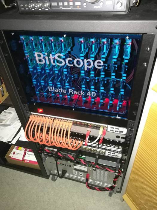
Thanks to OH2BNF for writing in and sharing his plan to build a "Large Scale Raspberry SDR" (LSR-SDR), which will be based on RTL-SDR dongles. To create the LSR-SDR he plans to take a 19" rack which can support up to 40 Raspberry Pi 3's, plus up to 160 USB devices, and turn it into a massive SDR array. The rack is key as it allows for simple power management of all the Pi's and other devices to be connected.
OH2BNF plans to connect 20 or so RTL-SDRs, with some operating individually and with others operating coherently via a common external oscillator. The rack may also contain some transceivers, an ICOM IC-7300, antenna switches, upconverters, LNAs and other hardware too. Once completed he hopes to move the system to a low RFI environment and operate the unit entirely remotely. With this he hopes to solve his local RFI issues. He also writes regarding applications:
Primary objectives are to incorporate automated adaptivity to the system at large – for example leveraging on band condition information, WSPR (Weak Signal Propagation Report) & friends, automated signal detection and decoding, great flexibility in terms of individual cluster nodes being able to fast respond to various needs and tasks, strong emphasis in parallel processing where applicable depending on the problem type and dataset, support for multiple end users benefiting from the computing and reception capacity of the cluster – to name the most significant.
It's an interesting idea for sure, and we hope to see some updates from OH2BNF in the future.