Thanks to the work of Lucas Teske, GQRX is now able to connect to SpyServer servers. SpyServer is the IQ streaming server software solution developed by the Airspy SDR developers. It can support Airspy and RTL-SDR devices, and can be used to access these SDRs remotely over a network connection. It is similar to rtl_tcp, but a lot more efficient in terms of network usage, meaning that it performs well over an internet connection. On a previous post we have a tutorial about setting up a SpyServer with an RTL-SDR.
The code modified by Lucas is the gr-osmosdr module, and Lucas' code can be downloaded from his GitHub at github.com/racerxdl/gr-osmosdr. It doesn't yet appear to have been merged into the official osmocom branch. The gr-osmosdr module is a generic block used to access various SDR hardware, so any software that utilizes it (such as GNU Radio) should be able to connect to a SpyServer connection too.
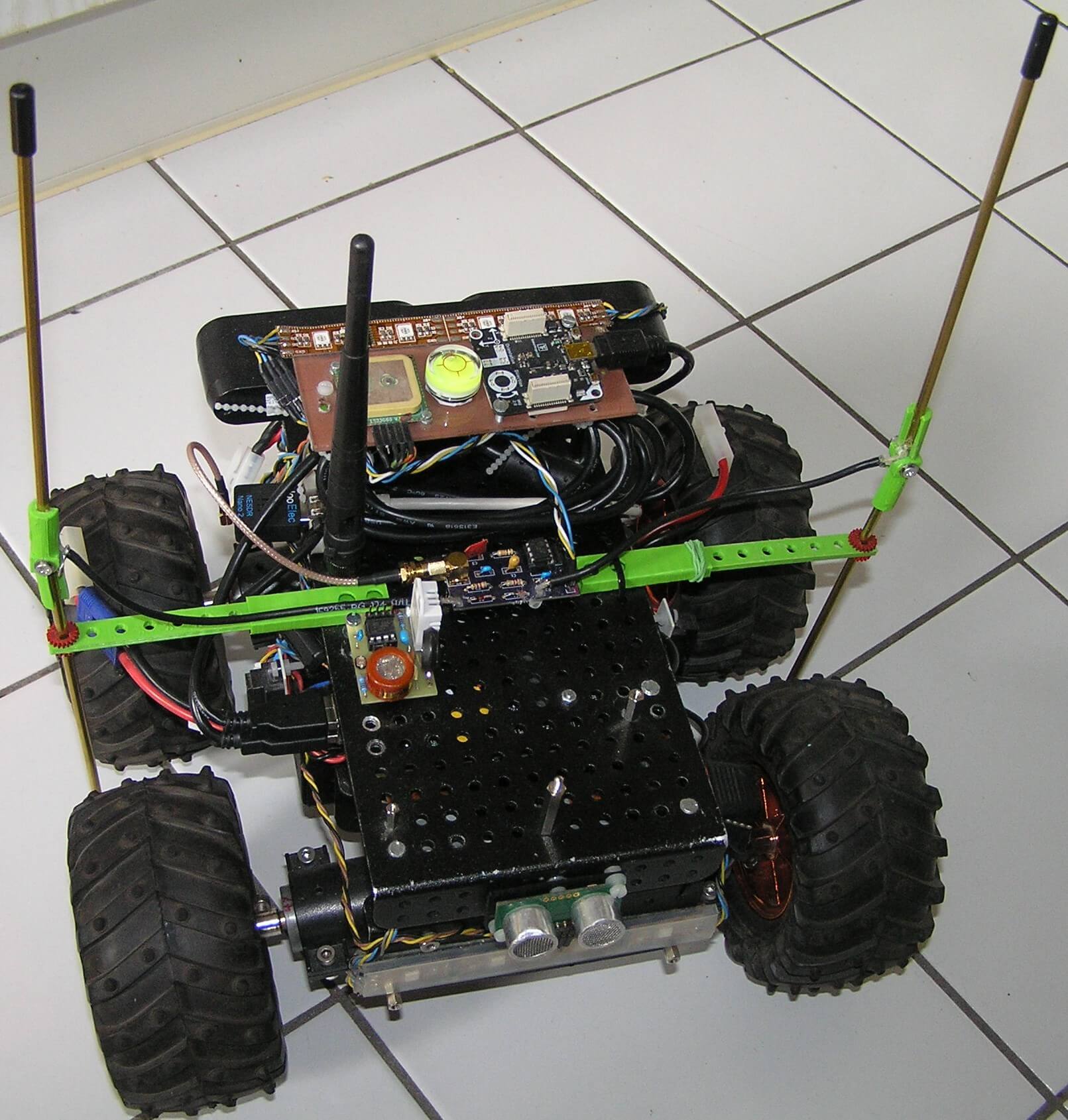
Over on Hackaday.io, project logger Humpelstilzchen has been writing about his attempts to create an autonomous RF direction finding robot RC car with an RTL-SDR. The goal is to set up an ISM band transmitter as a beacon, and use the RTL-SDR on the robot as the receiver. It will then use direction finding techniques to drive towards the beacon. The robot is a 4WD RC toy car with some autonomous navigational features like GPS, ultrasonic, IMU and vision sensors.
In his latest project log Humpelstilzchen describes his first semi-successful attempt at getting RF direction finding working. In the experiment he uses a 433 MHz module to send out an FSK beacon. On the robot two antennas are used for the time difference of arrival/pseudo-doppler direction finding technique, and PIN diodes are used to rapidly switch between the antennas. A GNU Radio script running on a HummingBoard single board computer computes the TDOA/pseudo-doppler algorithm.
Psuedo-doppler direction finding works by rapidly switching between several antennas. The difference in the time that the signal arrives at each antenna can be used to calculate the transmitter's direction.
With the current set up he's been able to get the robot to distinguish if the beacon is closer to the left, or closer to the right, or equidistant. However, he notes that there are still problems with reflections of the beacon signal which can cause the robot to drive in the wrong direction.
This is still a work in progress and we look forward to his future results.
QRP is amateur radio slang for 'low transmit power'. QRP digital modes such as FT8, JT9, JT65 and WSPR are modes designed to be transmit and received across the world on low transmit powers (although not everyone uses only low power). The special design of these modes allows even weak signals to be decodable by the receiving software. Released in 2017, FT8 has shown itself to now be the most popular mode by far with JT9 and JT65 taking a backseat. WSPR is also not as active as FT8, although WSPR is more of a beacon mode rather one used for making contacts.
Apart from being used by hams to make contacts, these weak signal modes are also valuable indicators of the current HF propagation conditions. Each packet contains information on the location of the transmitter, so you can see where and how far away the packet you've received comes from. You also don't need to be a ham to set up a monitoring station. As an SWL (shortwave listener), it can be quite interesting to simply see how far away you can receive from, and how many countries in the world you can 'collect' signals from.
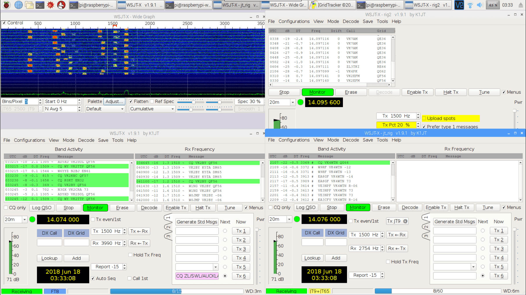
This tutorial is inspired by dg0opk's videos and blog post on monitoring QRP with single board computers. We'll show you how to set up a super cheap QRP monitoring station using an RTL-SDR V3 and a Raspberry Pi 3. The total cost should be about US $56 ($21 for the RTL-SDR V3, and $35 for the Pi 3).
With this setup you'll be able to continuously monitor multiple modes within the same band simultaneously (e.g. monitor 20 meter FT8, JT65+JT9 and WSPR all on one dongle at the same time). The method for creating multiple channels in Linux may also be useful for other applications. If you happen to have an upconverter or a better SDR to dedicate to monitoring such as an SDRplay or an Airspy HF+, then this can substitute for the RTL-SDR V3 as well. The parts you'll need are as follows:
RTL-SDR V3 (or upconverter, or other HF & Linux capable SDR)
Raspberry Pi 3 (or other SBC with similar performance)
Internet connection
Band filter (optional but recommended)
HF antenna (this could be as simple as a long wire)
Examples of QRP Receivers with an RTL-SDR
Monitoring FT8, JT9, JT65 and WSPR simultaneously with an RTL-SDR V3 and Pi 3
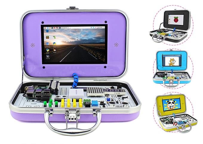
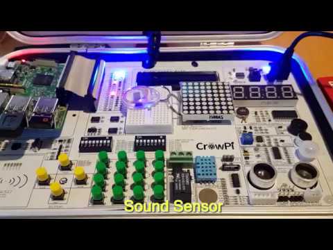
CrowPi is a Raspberry Pi all-in-one experimenters kit that is currently crowd funding on Kickstarter. The idea behind CrowPi is to combine a touchscreen, various sensors, actuators and interfaces into a clutter free kit mounted on a PCB in an easy to carry hard shell case. It's mostly intended to be used in STEM learning environments, however it could also be used for rapid prototyping of Raspberry Pi based ideas, or simply as a portable computer.
The CrowPi
The kit has 4 days left on Kickstarter and has already met its minimum goal. Pledging $1,169 HKD (~USD $150) gets you the basic kit which does not include a Raspberry Pi. Higher pledge levels (up to US$250) get you models that include a Raspberry Pi as well as extras such as a 5V power supplies, earphones, heatsinks, keyboards, game controllers etc. Shipping of the units is expected to commence in July.
Elecrow, the Shenzhen based company behind CrowPi kindly sent us a free kit for an honest review. While not directly related to RTL-SDR or RF, we thought that there might be several applications that might make the CrowPi kit useful for prototyping some simple low cost RF based ideas. For example:
Prototyping IoT based modules that use the RTL-SDR as a receiver. For example receiving a 433 MHz ISM signal and writing received information to the LCD/LED array or activating the relay.
Similarly, using FL2K-SDR or RPiTX to transmit a signal when a sensor is activated, or to transmit telemetry from that sensor (e.g. distance data from the ultrasonic sensor, humidity levels from the DH11 sensor, or light levels from the light sensor)
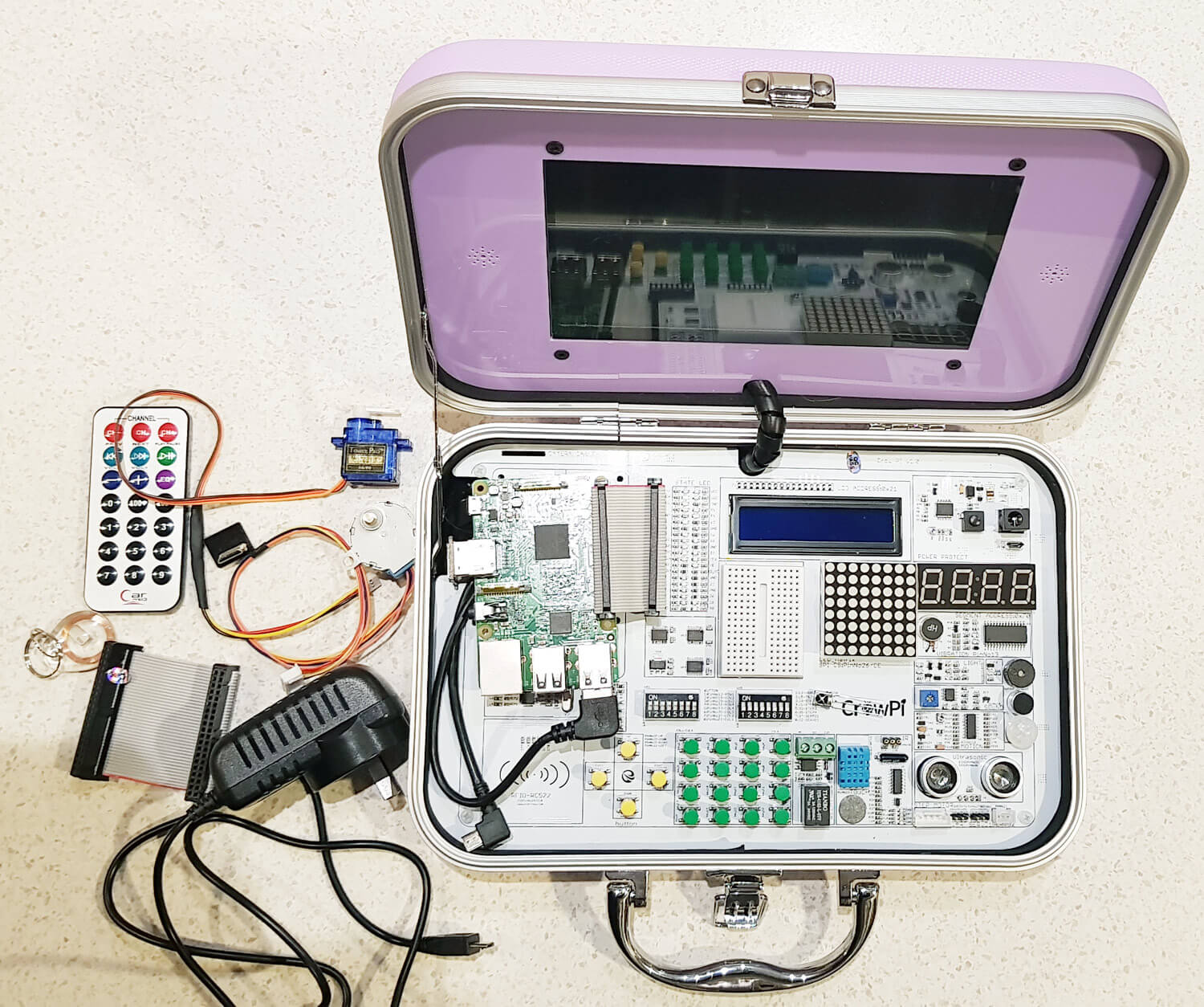
To get an idea of what's packed into the CrowPi, the kit includes the following modules:
Everything that came with our CrowPi Demo Kit (Except the Raspberry Pi)
1920 x 1080 Capable HDMI 7" Touch Screen
LCD Module
8x8 Matrix LED
Breadboard
4 character 7-seg LED
Vibration motor
Light Sensor
Buzzer
Sound Sensor
Motion Sensor
Ultrasonic Sensor
Servo Interface
Step Motor Interface
UART
Tilt Sensor
IR Sensor
Touch Sensor
DH11 Humidity Sensor
Relay
Matrix of buttons
RFID Module
With our kit we also received:
2x GPIO Flex Cables
1x Stepper Motor
1x Servo
1x Charger
1x IR diode
1x NFC Tag
1x Mini HDMI for the Raspberry Pi Zero
1x IR Remote control
Setup, Initial Testing and Thoughts
Setup: Setup was simple and consisted of downloading their customized Raspberry Pi image onto an SD card, connecting the Raspberry Pi to the HDMI, USB and GPIO pins, and then powering it up using the power jack on the CrowPi Board. A user manual is available for download.
Initial Testing: CrowPi provide a set of lessons that show how to use each of the modules on the board. All modules also have Python code examples that are ready to run as soon as you boot up. Immediately after booting up we were able to run their demo code which allowed us to test all the various sensors, print text to the LCD module, activate the 7-seg display, and actuate a servo and stepper motor.
The tutorials are easy to understand and provide a good basic rundown of the sensors. You will need to have some basic Python skills to understand the Python code however.
Thoughts: The CrowPi is built sturdy, and is definitely easy to use. The touch screen is bright and clear. It is capable of running in 1080P mode, but is a bit too small and hard on the eyes to use at this resolution. We kept the screen in 720P mode. In order to use the Raspberry Pi, you'll need to plug in a USB keyboard and mouse which is not included in the basic kit. A wireless keyboard/mouse combo is ideal. There appear to be speaker holes next to the monitor, but it seems that our demo model is the basic model which does not include built in speakers. The kit is impressive looking and appears to be priced reasonably for what you get.
RTL-SDR and RF Testing
Unfortunately when it came to run the RTL-SDR we instantly ran into a problem. With the one 5V 3A power supply running the Pi, HDMI Screen and modules, it seems that there just isn't enough power budget left over to run the RTL-SDR which draws about 270 - 290 mA current. The RTL-SDR connects fine, but when trying to run GQRX, the Pi 3 shuts down. To get around this problem we have to connect a second power supply directly to the Raspberry Pi 3's input. After doing this the board and kit runs smoothly with the RTL-SDR. Using a powered USB hub would also work.
RPiTX is software for the Raspberry Pi that allows you to transmit RF signals directly via PIN12 or PIN7 from the GPIO ports. On CrowPi PIN12 is already connected to the buzzer, and PIN7 is connected to the humidity sensor. Using PIN12 causes the buzzer to sound, so we tried PIN7. Even though it's connected to the humidity sensor, it doesn't seem to mind the GPIO bit flipping going on. The traces within the board and cable radiate sufficiently to transmit signals strongly enough to use within a room, so no external antenna is needed. Use of PIN7 can be activated in RPiTX by using the "-c 1" flag.
Using our Replay Attacks with an RTL-SDR, Raspberry Pi and RPiTX tutorial, we copied the signal from the remote control of a 433 MHz alarm/door bell, and used RPiTX to replay the signal. Then by modifying some of the supplied CrowPi Python code we were able to get the doorbell to sound on a touch of the touch sensor, activation of the sound sensor and via activation the RFID sensor. We could see the CrowPi being used as a general tool for learning how to prototype simple IoT or home automatic devices. The video below shows a brief demonstration.
It would have been nice if these RPiTX GPIO pins could have been exposed, and not connected to a sensor, but the developers of the board had probably not heard of RPiTX as the goal is for a more general classroom application.
CrowPi Demo
Conclusion
If you're looking to get kids or STEM students/hobbyists interested in what Raspberry Pi's can do, then this kit couldn't make it simpler. The single board and briefcase design makes the whole thing very tidy and portable and the kit looks and feels sturdy and professional. If you know a kid interested in electronics, then this kit would make a great present.
You could probably purchase all the components cheaper individually, but at the end of the day an all-in-one kit just makes sense as it is a lot tidier, and much easier to get up and running quickly.
For RF experiments, it's possible to use the RTL-SDR with the minor annoyance of having to connect two power supplies or use a powered USB hub. RPiTX also functions fine on the device and can be used to transmit an RF signal on activation of any one of the sensor modules. This could easily be used to prototype simple home automation or IoT ideas.
Osmocom, the team behind the original RTL-SDR driver project, the Osmo-FL2K discovery, OP25, gr-osmosdr, gr-gsm and various other open source cellular phone projects is now accepting monetary donations. If you weren't already aware, it was the efforts of Antti Palosaari and Eric Fry who made the original tests on DVB-T dongles, and then Osmocom who wrote the first RTL-SDR driver and software that is still currently used in the RTL-SDR project today. If you're interested, there is a full write up on the history or RTL-SDR at the bottom of rtlsdr.org.
The Osmocom project (if you count its predecessor OpenBSC) have been running for close to 10 years, creating a large number of Open Source projects related to mobile communications. We have never needed nor wanted any legal entity for it. It's a pure/classic FOSS project, open to contributions from anyone.
Until today, you could only contribute in one of the following forms:
by writing code (bug fixes, new features, etc) and submitting it (which means you need to be a developer)
by writing documentation / improving the wiki
helping other users on the mailing lists, IRC, or in other forums
donating cellular equipment (which many don't have)
hiring a freelancer or a company to write code and contribute to Osmocom on your behalf
buying products or services from companies who dedicate lots of work to Osmocom
However, we've repeatedly getting requests from some individuals who wanted to contribute to the project in an easy way, even if they are not a developer, and/or don't have time, and/or don't have the size of a budget to fund development of entire new features or sub-systems.
Today, Osmocom announces that we have joined Open Collective in order to enable you to make financial contributions, either one-off or recurring.
We'll be using the funds (if we get any!) according to our funding policy outlined at https://opencollective.com/osmocom/expenses/new# in order to pay for expenses such as hosting costs for our servers / IT infrastructure, travel funding for the annual developer conferences, etc. Any and all expenses paid from those funds will be visible on the OpenCollective website. You cannot ask for more transparency than that :)
Thanks in advance for your kind assistance!
So if you've ever enjoyed the RTL-SDR project, and how much it's improved your access to the RF spectrum, please consider donating via Open Collective or contributing back in other ways. Donations may help Osmocom to continue making new and interesting discoveries, such as Steve M's amazing FL2K-SDR discovery that was released back in April this year.
As Outernet is currently having a sale and selling their their moRFeus product at only US $99 (see next post for details - or simply use coupon code "rtlsdrblog" on their checkout - valid until Saturday 09 May 18), we thought that we'd show an interesting use for the moRFeus when combined with an RTL-SDR.
Outernet's moRFeus is a signal generator and frequency mixer that can be controlled either by it's built in LCD screen, or via software on a Windows or Linux PC. It can generate a clean low phase noise tone anywhere between 85 to 5400 MHz. Because it can be computer controlled it is possible to use moRFeus as a tracking generator for characterizing filters and measuring antenna SWR. A tracking generator is just a signal generator that can be set to output at the same frequency that the measurement receiver is tuned to.
In the past we've posted a tutorial showing how to use a wideband noise source for measuring filters and antenna SWR. However, if available, a tracking generator is usually preferred over a noise source. A wideband noise source outputs high power at all frequencies, and so can easily overload an RTL-SDR causing reduced dynamic range and accuracy in measurements. This is especially the case when measuring bandstop filters as they pass all frequencies, apart from a small blocking band. Since so much noise gets through to the dongle, dynamic range is reduced.
This post shows how to use the moRFeus as a tracking generator together with an RTL-SDR for making RF measurements. This could be called a scalar network analyzer. The set up uses GQRX and a Python script, but in the future it is possible that someone may develop a standalone app.
Since the output of the moRFeus is quite strong, an attenuator is required to keep signal levels low enough to not overload the RTL-SDR.
The cheapest RF bridge we've found is available on eBay for about $7. With an RF Bridge you'll need a 50 Ohm dummy load as well to connect to the 'REF' port. Directional couplers seem to work more accurately however, and second hand minicircuits ones can often be found on eBay. A $2 TV 'tap' is also a directional coupler, and may also work, although we have not tested this.
Software Setup
In this tutorial we're using the method first described by 'LamaBleu' in his post to the Outernet forums. The method uses Linux and involves reading power levels from the RTL-SDR by using GQRX and it's remote telnet connection capabilities. The telnet command "F freq" can be used to change frequency in GQRX, and the command "l" can be used to read out the current power level in dbFS.
To control moRFeus we use Outernet's official "morfeus_tool", which is a command line based tool.
A basic Python script was written to set the frequency in moRFeus and GQRX at the same time. After a 500 ms settling time the power level is measured and recorded in a CSV file, then the script iterates to the next frequency. We iterate at 1 MHz intervals.
If you have a moRFeus and want to try this project out, copy and paste the script from pastebin, and name the file morfeus_scalar.py. Place the morfeus_scalar.py file and the morfeus_tool_linux_x32 tool into the home folder.
To get the software started:
Open GQRX and connect the dongle and required RF components for the test (shown below).
Set the RTL-SDR gain to zero or just low enough so that the signal doesn't cause overload (moRFeus signal levels are fairly high).
In the GQRX GUI ensure that the "Remote control via TCP" button is pressed in. (Looks like two computer screens).
Edit the Python script and choose the frequency range that you'd like to scan by setting variable FREQ_MIN and FREQ_MAX.
In a terminal run "sudo python morfeus_scalar.py".
When the script completes you'll have a file "out.txt" which is a CSV file of frequency and signal power levels.
Characterizing Filters
To characterize a filter (find the response of a filter) simply connect the system like so:
moRFeus Filter Test
But first connect just the moRFeus, attenuator and RTL-SDR together.
In GQRX increase the gain until just a few dB before the RTL-SDR overloads and starts showing signal images. This will maximize the available dynamic range.
Run an initial calibration scan with morfeus_scalar.py. Save the results in out.txt into a spreadsheet.
Connect the filter in the RF chain, and then run a second scan with morfeus_scalar.py. Save the results into another column in the spreadsheet.
Subtract the calibration scan results from the filtered results. Plot the resulting values using the spreadsheet software. This will show the response of the filter.
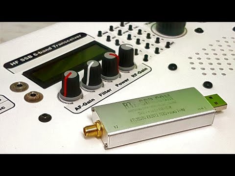
Over on YouTube OM0ET has shown how he uses his RTL-SDR for measuring crystals. While working on his home made HF 6-band SSB transceiver, OM0ET needed a way to measure the frequency of some 8 MHz crystals that he needed for his IF filter.
To perform the measurement he simply inserts the crystal into a homemade oscillator circuit, and measures the output with an RTL-SDR V3 operating in direct sampling mode. With the measurements he's able to figure out if the crystal is actually working in the first place, and secondly determine an accurate frequency measurement.
RTL-SDR USB receiver - cheap tool for matching crystals
Inspired by a low flying aircraft that kept waking his cat in the morning, Simon Aubury decided to use an RTL-SDR and ADS-B tracking software dump1090 to determine which plane was the culprit. This is all now standard stuff, however, Simon's software implementation and management of the received ADS-B data is quite unique, as he uses Apache Kafka, KSQL and Kibana as his tools for processing and visualizing the ADS-B data.
Apache Kafka is a 'distributed streaming platform', and KSQL enables real time processing of the data from Kafka. Kibana is a data visualization tool. Essentially these technologies are just ways to manage, process and digest in a human readable way large amounts of real time data coming into a database.
So with some clever database coding Simon was able to create a constantly updating dashboard in Kibana that plots aircraft positional heat maps, displays data such as spotted airlines and destination frequencies in a text cloud, and displays aircraft height data in a line graph. Finally using a database lookup and his gathered data Simon was able to determine that an A380 aircraft flying over his house was waking his cat in the morning.