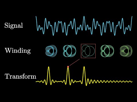
The Fourier Transform is a fundamental concept when it comes to digital signal processing (DSP) and thus understanding how software defined radios like the RTL-SDR work. It is the key bit of maths behind the RF/waterfall spectrum displays and frequency selection features used on your SDR software. In basic terms all the Fourier Transform does is take a signal (for example an RF signal from an antenna, or a sound sample), and break it down into its component frequencies. This allows us to see each individual frequency spike in the RF/waterfall spectrum display in programs like SDR# from the mash of signals that arrive at the antenna. But understanding how the Fourier Transform does this can be a little tricky to understand.
3Blue1Brown is a very successful YouTuber whose channel is all about explaining complex mathematical concepts in an animated and easy to digest format. His latest video explains the Fourier Transform, and is a great starting point for those trying to learn DSP concepts. He focuses on audio frequencies as that is the most intuitive, but the exact same concepts can be applied to radio frequencies.
But what is the Fourier Transform? A visual introduction.
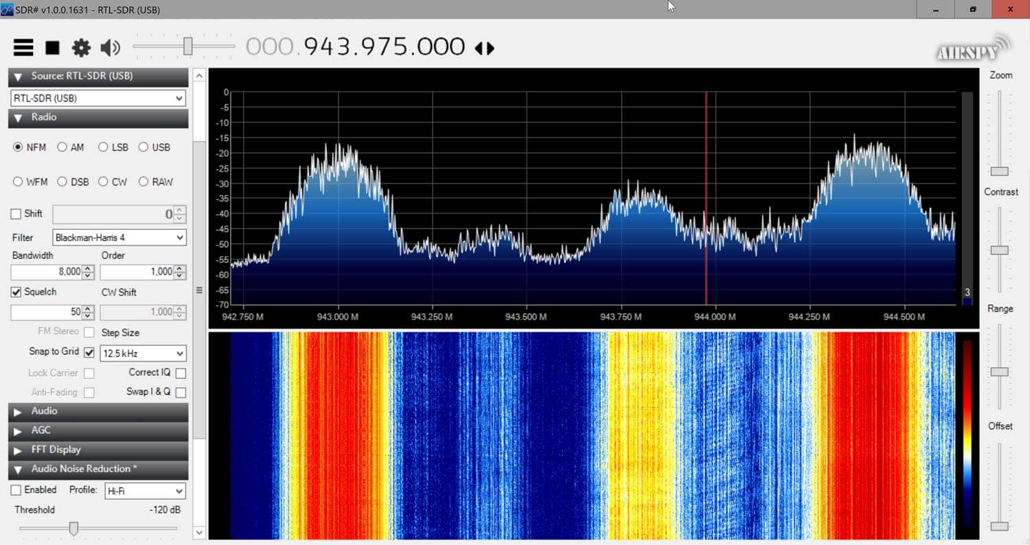
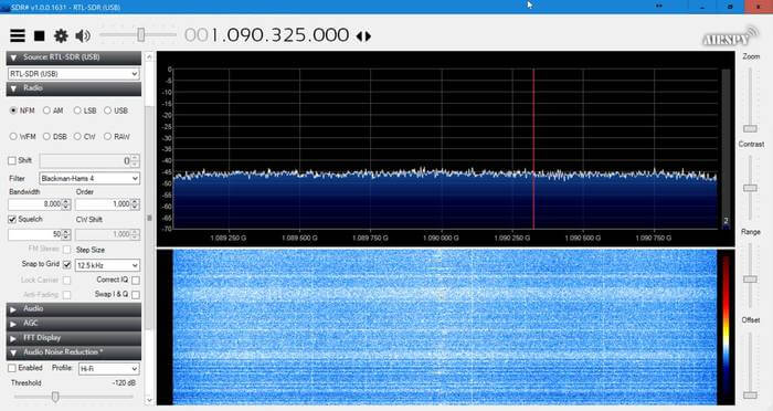
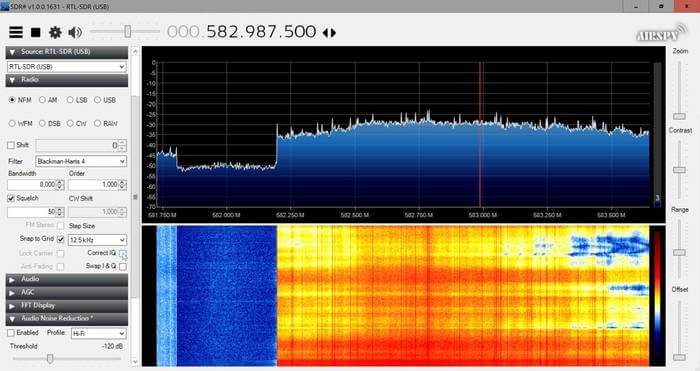
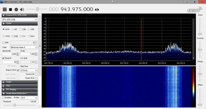
Thank you to an anonymous contributor for sharing his experiences with trying to receive satellite TV beacons with his RTL-SDR. Satellite TV is typically up at 10.7 to 11.7 GHz which is far too high for an RTL-SDR to receive. So to receive these frequencies with the RTL-SDR he uses a satellite TV LNB (an LNB is essentially a downconverter and satellite dish feed), a DIY Bias T and a 90 cm dish. He writes:
Almost all television satellites have a special frequency for transmitting a beacon signal. The beacon signal is a reference signal with fixed frequency, power and [maybe] without modulation that is sent usually by satellites. One of the most important techniques used for satellite wave propagation studies is satellite beacon signal measurement. (http://eej.aut.ac.ir/article_433.html)
I used an universal LNB, DIY bias-T and a fixed 90cm dish pointed at 26 degrees East. By connecting 18 volts DC to LNB I am able to activate the 9750 Mhz local oscillator and horizontal operating mode of LNB.
Means that anything received with LNB between 10.7-11.7 GHz can be easily seen in 950-1950 MHz range, using RTL-SDR.
It is useful for measuring attenuation caused by heavy rain in Ku band or accurate dish positioning or even measuring frequency drift in LNB local oscillator caused by wind and temp change during a timespan.
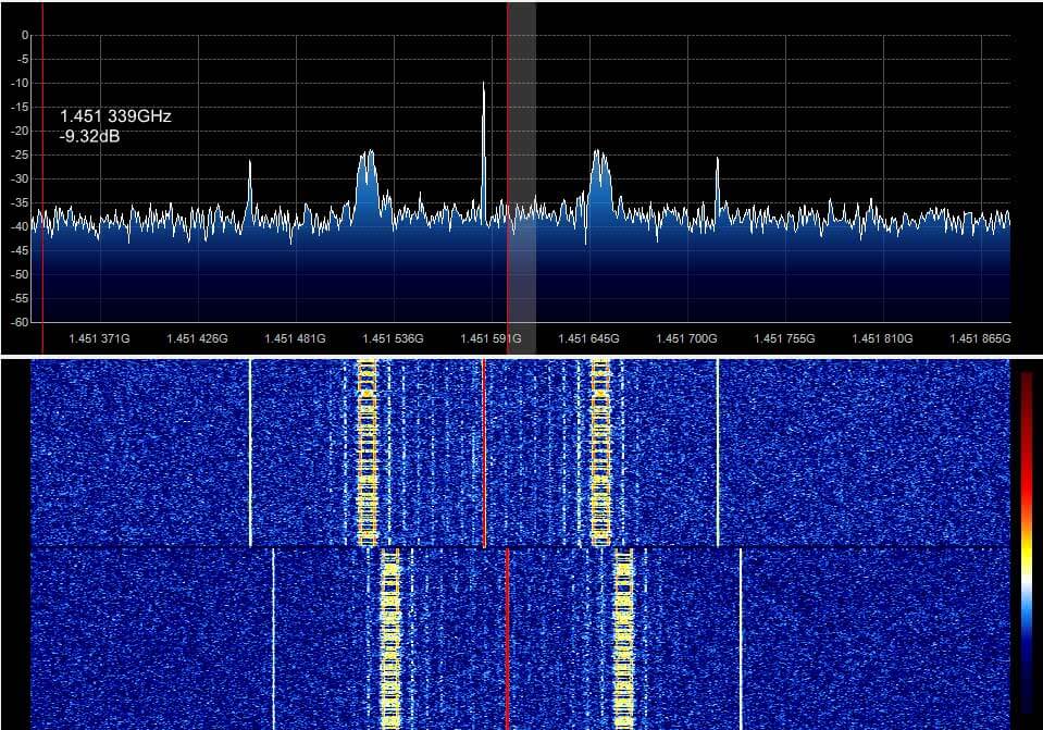
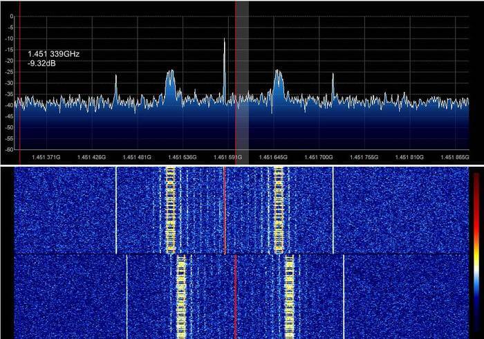
It seems that the right signal is Eutelsat 21B and left Es'hail 1.
In picture 4 signal captured immediately after turning on LNB. but all others are captured after at least 5 hours of warming up.
MAYBE oscillator needs a stabilize time or temp change may caused the drift.
If you are interested in receiving these beacons, Daniel Estevez has also performed similar experiments with his RTL-SDR and an LNB as well, and has written about it on his blog.
Below we show some images of beacons shown in SDR# that the anonymous contributor received with his setup.
The Fourier Transform is a fundamental concept when it comes to digital signal processing (DSP) and thus understanding how software defined radios like the RTL-SDR work. It is the key bit of maths behind the RF/waterfall spectrum displays and frequency selection features used on your SDR software. In basic terms all the Fourier Transform does is take a signal (for example an RF signal from an antenna, or a sound sample), and break it down into its component frequencies. This allows us to see each individual frequency spike in the RF/waterfall spectrum display in programs like SDR# from the mash of signals that arrive at the antenna. But understanding how the Fourier Transform does this can be a little tricky to understand.
3Blue1Brown is a very successful YouTuber whose channel is all about explaining complex mathematical concepts in an animated and easy to digest format. His latest video explains the Fourier Transform, and is a great starting point for those trying to learn DSP concepts. He focuses on audio frequencies as that is the most intuitive, but the exact same concepts can be applied to radio frequencies.
But what is the Fourier Transform? A visual introduction.
Thank you to an anonymous contributor for sharing his experiences with trying to receive satellite TV beacons with his RTL-SDR. Satellite TV is typically up at 10.7 to 11.7 GHz which is far too high for an RTL-SDR to receive. So to receive these frequencies with the RTL-SDR he uses a satellite TV LNB (an LNB is essentially a downconverter and satellite dish feed), a DIY Bias T and a 90 cm dish. He writes:
Almost all television satellites have a special frequency for transmitting a beacon signal. The beacon signal is a reference signal with fixed frequency, power and [maybe] without modulation that is sent usually by satellites. One of the most important techniques used for satellite wave propagation studies is satellite beacon signal measurement. (http://eej.aut.ac.ir/article_433.html)
I used an universal LNB, DIY bias-T and a fixed 90cm dish pointed at 26 degrees East. By connecting 18 volts DC to LNB I am able to activate the 9750 Mhz local oscillator and horizontal operating mode of LNB.
Means that anything received with LNB between 10.7-11.7 GHz can be easily seen in 950-1950 MHz range, using RTL-SDR.
It is useful for measuring attenuation caused by heavy rain in Ku band or accurate dish positioning or even measuring frequency drift in LNB local oscillator caused by wind and temp change during a timespan.
It seems that the right signal is Eutelsat 21B and left Es'hail 1.
In picture 4 signal captured immediately after turning on LNB. but all others are captured after at least 5 hours of warming up.
MAYBE oscillator needs a stabilize time or temp change may caused the drift.
If you are interested in receiving these beacons, Daniel Estevez has also performed similar experiments with his RTL-SDR and an LNB as well, and has written about it on his blog.
Below we show some images of beacons shown in SDR# that the anonymous contributor received with his setup.
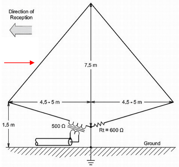
Thank you to Frank Sessink (PA0FSB) for submitting to us his document describing the K9AY loop antenna (pdf), which is the antenna that he successfully uses with his RTL-SDR for HF reception. The antenna combines magnetic (H) and electric (E) field reception in order to create a directive radiation pattern. Frank extends the idea by showing a method that can adjust the directivity electrically with some simple resistor switching.
The antenna that I use is for medium wave DX, specially to receive MW from USA here in Europe/The Netherlands. The antenna is a combination of a magnetic loop and a sense antenna for the E-field. The magnetic loop is directive, but has no front-rear ratio. The E-field antenna has omnidirectional sensitivity. The combination, in correct phase and amplitude, results in a front-rear ratio of more than 25 dB over the frequency range from 500 kHz to around 3 MHz. Higher frequency makes no sense, since skywave signals distort the ground wave directivity pattern.
A simple modification is used as directional antenna with remote control: two orthogonal loops that combine E and H-field in a simple way. I can make 8 selectable directions.
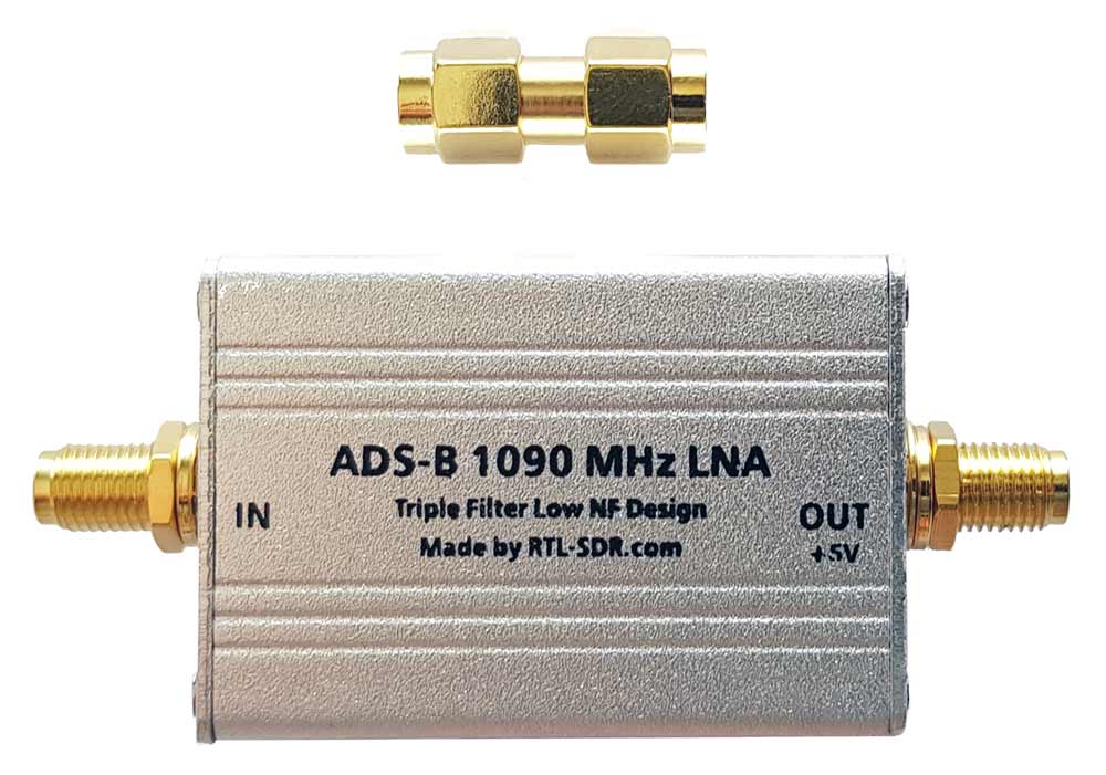
We're happy to announce the release of our new high performance low noise amplifier (LNA) for improving 1090 MHz ADS-B reception. The LNA uses a low noise figure high linearity two stage MGA-13116 amplifier chip and three stages of filtering to ensure that strong signals or interference will not overload either the amplifier or SDR dongle.
The LNA is currently only available from our Chinese warehouse, and costs US$24.95 including shipping. Please note that the price may increase slightly in the future, and that Amazon USA may not be stocked until March.
An LNA can help improve ADS-B reception by reducing the noise figure of the system and by helping to overcome losses in the coax cable and/or any other components such as switches and connector in the signal path. To get the best performance from an LNA, the LNA needs to be positioned close to the antenna, before the coax to the radio.
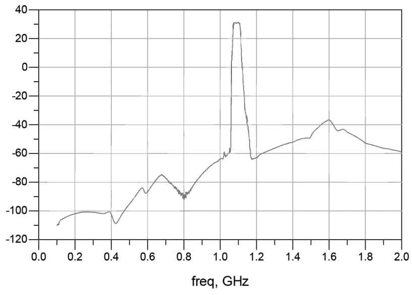
The gain of the RTL-SDR Blog ADS-B LNA is 27 dB's at 1090 MHz, and out of band signals are reduced by at least 60 - 80 dB's. Attenuation in the broadcast FM band and below 800 MHz is actually closer to over 100 dB's. In the LNA signal path there is first a low insertion loss high pass filter that reduces the strength of any broadcast FM, TV, pager or other similar signals that are usually extremely strong. Then in between the first and second stage of the LNA is a SAW filter tuned for 1090 MHz. A second SAW filter sits on the output of the LNA. The result is that strong out of band signals are significantly blocked, yet the LNA remains effective at 1090 MHz with a low ~1 dB noise figure.
The LNA is also protected against ESD damage with a gas discharge tube and low capacitance ESD diode. But please always remember that your antenna must also be properly grounded to prevent ESD damage.
Please note that this LNA requires bias tee power to work. Bias tee power is when the DC power comes through the coax cable. The RTL-SDR V3 has bias tee power built into it and this can be activated in software. See the V3 users guide for information on how to activate it. Alternatively if you don't own a dongle with bias tee built in, then an external bias tee can be used and those can be found fairly cheaply on eBay. Finally, if you are confident with soldering SMT components, then there are also pads and a 0 Ohm resistor slot on the PCB to install an LDO and power the LNA directly.
In addition please remember that this is a high gain LNA. It is expected to be used at the antenna side, with some 3+ db loss expected on the coax. However, if desired, it can still be used on the receiver side. If used on the receiver side or with a low loss run of coax, you will need to tune the RF gain on the RTL-SDR dongle. By default most software sets the RF gain to maximum. We recommend turning the RTL-SDR RF gain down to about 32 dB if connecting it directly to the dongle, otherwise the high input power may overload the dongle causing poor performance.
Specification Summary:
Frequency: 1090 MHz
Gain: 27 dB @ 1090 MHz
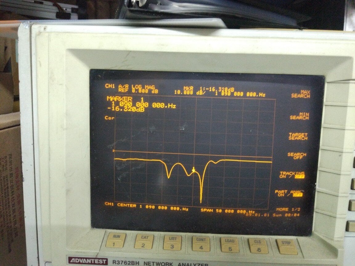
Return Loss: -16 dB @ 1090 MHz (SWR = 1.377)
Noise Figure: ~1 dB
Out of band attenuation: More than 60 dB
ESD Protection: Dual with GDT and ESD Diode
Power: 3.3 - 5V via bias tee only, 150 mA current draw
Enclosure: Aluminum enclosure
Connectors: Two SMA Female (Male to Male adapter included)
Dimensions:
46.5 x 32 x 15.6 mm (not including the SMA).
Including the SMA the length is 69.8 mm.
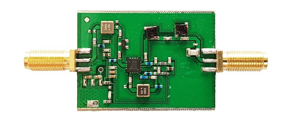
Testing
We tested our new LNA against another ADS-B LNA with filter built in that is sold by another company and the FlightAware Prostick+ dongle in an environment with strong out of band signals such as pagers, broadcast FM, DVB-T and GSM signals. The results showed that the RTL-SDR Blog ADS-B LNA gathered the most ADS-B packets. In the tests both LNA's were connected on the receiver side to be fair to the FA dongle. Improved performance could be achieved by moving the LNA to the antenna side.
Other ADS-B LNA vs RTL-SDR Blog ADS-B LNA Received MessagesFlightAware Prostick+ vs RTL-SDR Blog ADS-B LNA Received Messages
Checking in SDR# for out of band signals also showed that the RTL-SDR Blog ADS-B LNA significantly reduces those strong out of band signals, whereas the others have trouble blocking them out. Below we show the results as well as some measurements.
This RTL-SDR Blog ADS-B LNA can significantly improve ADS-B reception, especially if you are in an environment with strong out of band signals. Even if you are not, the low noise figure design will improve reception regardless.
Thanks to RTL-SDR.com reader Henry for letting us know about the release of a new piece of Windows software by Tag Loomis (N0TTL) called GridTracker. GridTracker is a live mapping program for WSJT-X which is a software decoder for low power weak signal ham communications modes such as FT8, JT4, JT9, JT65, QRA64, ISCAT, MSK144 and WSPR. Although these are low power modes, the protocols are designed such that even weak signals can potentially be received from across the world. Mapping the received signals can be interesting as it may give you an idea of current HF propagation conditions.
GridTracker is a Windows (XP or above) companion program for WSJT-X. It listens to WSJT-X or JTDX decodes and displays them on a map.
A great way to visualize communicating amateurs around the world!
Display on a large second monitor in your amateur radio club, hamfest or as a demonstration in a classroom. Everyone gets excited when they can see what you’re doing!
You can also load your ADIF log files from WSJT-X, Qrz.com, LoTW, PSKReporter and others to get a visual view of ‘stations worked’, stations that can hear you and more!
It might be an interesting project to set up a permanent GridTracker display using an RTL-SDR V3 in direct sampling mode, or RTL-SDR with upconverter. Low cost x86 single board PCs that can run Windows 10 such as the LattePanda, UP board or Udoo might be possible candidates for host hardware.
Henry warns us that the software is still new, so it may be a little buggy.
GridTracker Mapping out Weak Signal Communications.
Back in December Tysonpower showed us how he was able to receive HRPT weather satellite images with a 80cm and 1.2m satellite dish, LNA and Airspy Mini.
If you didn't already know, HRPT signals are a little different to the more commonly received NOAA APT or Meteor M2 LRPT images which most readers may be more familiar with. HRPT images are more difficult to receive as they are broadcast in the L-band at about 1.7 GHz and so receiving them requires a dish antenna (or high gain Yagi antenna), L-band dish feed, LNA and a high bandwidth SDR such as an Airspy Mini. The result is a high resolution and uncompressed image with several more color channels compared to APT and LRPT images.
In the last video Tysonpower was successful with receiving HRPT images with his setup. But recently over on his YouTube channel and on his blog Tysonpower has shown how he has improved his HRPT reception by first optimizing the feed and adding in a copper matching line which helps improve the impedance matching of the feed. He also added an L-Band filter tuned to the HRPT signal which he notes made the biggest improvement, and he also moved all the components into a watertight box for permanent outdoor mounting. With these changes he's now able to consistently pull in some very nice imagery. All the images are still received by hand tracking the satellite dish as the satellite passes over, but he notes that he plans to experiment with motorized trackers in the future.
Note that the video shown below is narrated in German, but English subtitles are provided if you turn on YouTube captions.
[EN subs] HRPT - optimierungen und sehr gute Bilder
A sample HRPT image received by Tysonpower.
In addition to the above Tysonpower also writes that he has created a free HRPT decoder for the HRPT signals originating from NOAA satellites. He writes regarding HRPT decoders:
I found it quite complicated to find a decoder for HRPT when i started and there is still no one that you can just Download.
The only free Decoder is the gr-noaa example in gnu radio that has a depricated wx GUI and uses a input from a specific SDR. I used that gr-noaa example and created a decoder that uses the modern QT GUI and has a clean interface. You just put in a wav IQ file from SDR# for example and it will decode the Data into the file you entered. It is not the best one out there in form of signal processing, but a good start i would say.
The decoder can be downloaded from tynet.eu/hrpt-decoder. Below is a second YouTube video where Tysonpower explains how to use the decoder.
[EN subs] Kostenloser HRPT Decoder (GNU Radio) - Und wie man ihn nutzt
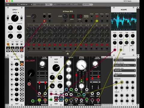
VCV Rack is an open source virtual modular synthesizer, which is software that can be used to create synth music or sounds. The interface is modeled after physical synthesizers called Euroracks. Recently, Jon Williams has ported rtl_fm to the VCV Rack plugin system which allows him to include live FM music in the synthesizer output. This can be used to create some interesting sounds which he demonstrates on the video that is shown below. The frequency tuning is 'voltage controlled', which simply means that it can be adjusted with a knob in the software.
Over on his YouTube channel Adam 9A4QV has uploaded a video showing how an LNA work to improve signal SNR on VHF, as long as the LNA is placed close to the antenna. Adam is the manufacturer and seller of the popular LNA4ALL low noise amplifiers.
On UHF and high frequencies an LNA can help by reducing the system noise figure, but on VHF this effect is small. But if the LNA is placed near the antenna then the LNA can still help significantly by overcoming any losses in the coax cable, filters, switches or any other lossy components in the signal path. It might also help create a better SWR match for the dongle and antenna. The video has some sound issues in during the demonstration part, but on his Reddit thread Adam writes:


![[EN subs] HRPT - optimierungen und sehr gute Bilder](https://www.rtl-sdr.com/wp-content/plugins/wp-youtube-lyte/lyteCache.php?origThumbUrl=https%3A%2F%2Fi.ytimg.com%2Fvi%2FHcaJgFatKQI%2F0.jpg)
![[EN subs] Kostenloser HRPT Decoder (GNU Radio) - Und wie man ihn nutzt](https://www.rtl-sdr.com/wp-content/plugins/wp-youtube-lyte/lyteCache.php?origThumbUrl=https%3A%2F%2Fi.ytimg.com%2Fvi%2FxtNu3rV1FEY%2F0.jpg)