Tagged: rtl-sdr

RTL-SDR Tutorial: Setting up and using the SpyServer Remote Streaming Server with an RTL-SDR

A number of people have asked how to use SDR#'s SpyServer with an RTL-SDR. In this tutorial we will show how to set up SpyServer on both Windows and Linux systems. We try to assume as little knowledge as possible, but we do assume that you have decent experience with computers. Also for the Linux/Raspberry Pi setup we need to assume that you have some basic experience with Linux and setting up Raspberry Pi's.

What is SpyServer?

SpyServer is a free RTL-SDR compatible SDR server that is designed to work with the popular SDR# software. It is actually designed for the Airspy range of products, but the author has also made it compatible with RTL-SDR dongles. Running a SpyServer allows you to connect to and use a remotely positioned RTL-SDR over a network connection (such as a local LAN/WiFi or the Internet). Once connected, using the dongle is the same as if the dongle was directly connected to the users PC.
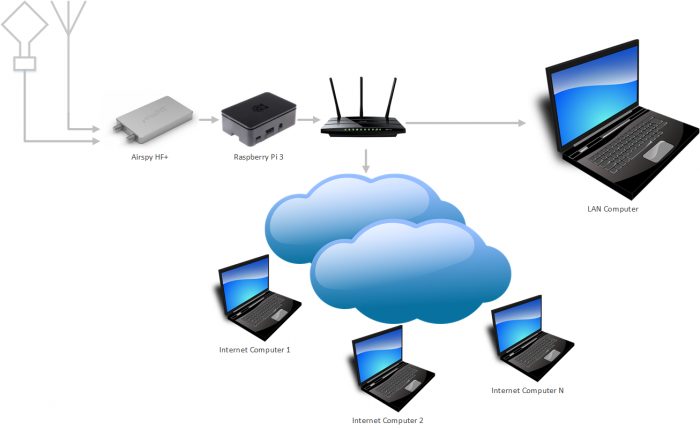
An example SpyServer Overview
An example SpyServer Overview (Can use an RTL-SDR instead of the Airspy HF+)

Remote servers are useful as you may want to set up an antenna in a remote location (such as up on your roof or shack), and don't want to run a long lossy coax cable down to the PC. Instead you could run Ethernet cable, or avoid cables by using WiFi. All you'd need is power for a remote computing device like a Raspberry Pi 3. Perhaps you also have a great antenna location at a friends house, or other property and want to access that antenna remotely. Or maybe you want to use your radio while travelling.

SpyServer is similar to another tool that you may already be familiar with called rtl_tcp. However, SpyServer is regarded as superior because it is signficantly more efficient at network usage. Instead of sending the entire raw data like rtl_tcp does, SpyServer only sends the IQ data of the currently tuned in signal. Waterfall data is processed on the server and sent in compressed form. There is one disadvantage to SpyServer in that it requires slightly more powerful computing hardware like a Pi 2 or Pi 3, whereas rtl_tcp can run on the lowest end hardware.

Network usage when streaming with SpyServer will be about 120 KB/s when listening to WFM and about 38 KB/s when listening to narrow band modes for one client being connected. Multiple clients can connect to the SpyServer and share the same currently tuned bandwidth.
Continue reading

Using an RTL-SDR and RPiTX to Defeat the Rolling Code Scheme used on Some Subaru Cars

Over on GitHub Tom Wimmenhove has been experimenting with the car keyfob on his Subaru car, and has discovered that the rolling code scheme used is very weak and so can be easily exploited.

Most modern vehicles use some form of rolling code security on their wireless keyfobs to prevent unauthorized replay attacks. When the car owner presses a button on the keyfob, a unique rolling code is sent to the car. If it matches one of the codes currently stored in the car, the car will unlock and then invalidate that code so it can never be used again, thus preventing a replay attack. On the next press the keyfob sends a new code. In most designs when a code is used up, a new code is added to the list of valid codes via a random number generator based on a secure algorithm only known (presumably) to the engineers.

Essentially Tom found that instead of producing a randomly generated rolling code, the Subaru keyfob simply increments the rolling code number each time. This allows an attacker to perform a second key press simply recording an initial real key press, decoding the packet, increasing the decoded rolling code by one, then re-transmitting. It also means that the attacker could continually raise the rolling code value on the car himself, which would eventually make the real keyfob useless as the codes on the keyfob would be outdated and no longer match the same number range as the car.

The entire exploit was found on a super low budget. Tom used only an RTL-SDR and Raspberry Pi. The receive is obviously handled by the RTL-SDR, but the transmit side is handled by RPiTX which is software that allows the Raspberry Pi to transmit RF signals directly from a GPIO pin without the need for any additional transmitting hardware. Tom writes that the exploit probably affects the 2006 Subaru Baja, 2005 - 2010 Subaru Forester, 2004 - 2011 Subaru Impreza, 2005 - 2010 Subaru Legacy and the 2005 - 2010 Subaru Outback. Tom also writes that various dealers and spokes people have contacted him stating that the exploit probably only affects US models. If you have one of the affected models and are worried the only way to stay safe is to simply not use wireless entry on the keyfob, at least until/if Subaru fixes the issue with a recall. Although so far no statement from Subaru has been released.

Tom has also uploaded a demonstration video to YouTube which is shown below.

[Also seen on Hackaday, Bleeping Computer and The Register]


Subaru fobrob exploit

Testing a 16x RTL-SDR V3 WebSDR System for the Satcom Band

Over on Twitter Denis (@uhfsatcom) has recently been teasing us with photos of his 16 dongle RTL-SDR V3 setup. The system looks like it's designed to be a satcom band WebSDR receiver. 

The satcom band is around 240 - 270 MHz and mostly consists of various military satellites that act as simple repeaters which are often hijacked by pirates. WebSDR is a piece of software that allows for online web streaming of SDR radios. Users from all over the world can listen in if made public. Denis has also uploaded a short video showing a test of 8 dongles running and receiving the satcom band on his WebSDR system.

We look forward to hearing more updates on this project!

8 rtlsdr websdr test

RadioForEveryone New Posts: Antenna Weatherproofing, NooElec Nano 3 Review, ADS-B Antenna Shootout

Over on his blog 'Radio for Everyone' author Akos has uploaded three new posts. The first shows how to cheaply weatherproof antenna connections by wrapping electrical/plumbing tape around the connection. He shows and example with the FlightAware ADS-B antenna.

The second post is a review of the relatively new NooElec Nano 3, which is a small form factor RTL-SDR that comes with a TCXO and metal case. Akos shows how the form factor is good for using it with Mobile phones. Akos opens the unit up and shows us how the unit is sandwiched inside the metal case with two thermal pads for improved heat dissipation. Later in the review he also discusses the MCX connector, TCXO and heat.

The third post compares three commercially sold antennas at ADS-B reception. The compared antennas are the FlightAware ($45) and Jetvision ($90) ADS-B antennas as well as our RTL-SDR Blog general purpose dipole ($10). The results show that the Jetvision antenna performs the best followed by the FlightAware and then the dipole. However we note that Akos has incorrectly used the dipole as he did not orient it as a vertical dipole.

Radio For Everyone: Nano 3 Size Comparison

Meteor Logger: A Tool for Counting Meteor Detections with an RTL-SDR

Thanks to Wolfgang Kaufmann for submitting news about his new software called ‘Meteor Logger’. This tool can be used to count the number of meteors entering the atmosphere which have been detected by a meteor scatter setup using an RTL-SDR or similar SDR.

Wolfgang writes about his software:

I have developed a new piece of software “Meteor Logger” to detect and log radio meteors from the digital audio stream of a PC-soundcard. It is based on Python 3. It is addressed to those meteor enthusiasts who want get the most information out of forward scattering of radio waves off meteor trails. “Meteor Logger” do not display spectrograms, it delivers an instantaneous and continuous numerical output of the detected signal with a high time resolution of about 11 ms. Thereby a radio meteor signal is not detected on the basis of an amplitude threshold but on its signature in the frequency domain. “Meteor Logger” has a built in auto notch function that may be helpful in case of a persistent strong interference line. From these data not only hourly count rates can be derived but it is also possible to easily study power profiles of meteors as well as Doppler shifts of head echoes.

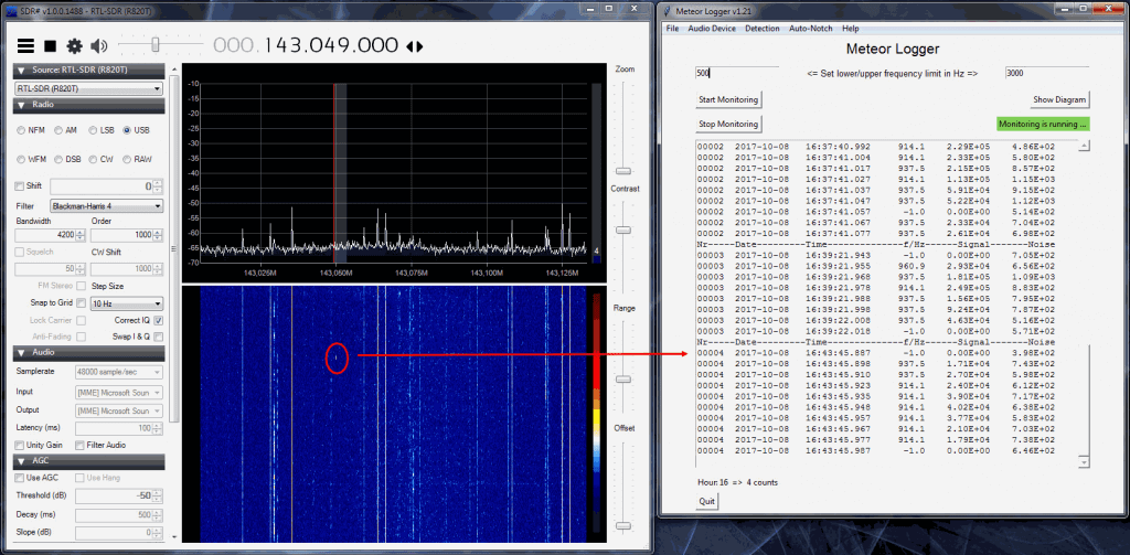
As receiving front end a RTL-SDR is fine, if you strive after a very high signal resolution you may use a Funcube Dongle Pro. I employed SDR# to run the RTL-SDR. GRAVES-radar is used as transmitter. The added screenshot shows this setup together with “Meteor Logger”.

Additionally I wrote an also Python 3 based post processing software “Process Data” that allows for clearing the raw data, viewing and analysing them and exporting them in different ways (e.g. as RMOB-file for opening with “Cologramme Lab” of Pierre Terrier, see added screenshot).

Everything else you may find on my website http://www.ars-electromagnetica.de/robs/download.html

Meteor Logger
Meteor Logger

Meteor scatter works by receiving a distant but powerful transmitter via reflections off the trails of ionized air that meteors leave behind when they enter the atmosphere. Normally the transmitter would be too far away to receive, but if its able to bounce off the ionized trail in the sky it can reach far over the horizon to your receiver. Typically powerful broadcast FM radio stations, analog TV, and radar signals at around 140 MHz are used. Some amateur radio enthusiasts also use this phenomena as a long range VHF communications tool with their own transmitted signals. See the website www.livemeteors.com for a livestream of a permanently set up RTL-SDR meteor detector.

Testing the Prototype Outernet Patch Antenna with Built in RTL-SDR

A few months ago satellite data broadcasting company Outernet created a limited number of prototype receivers that combined an L-band satellite patch antenna, LNA and RTL-SDR into a signal unit. This was never produced in bulk as they found it to be too noisy having the RTL-SDR so close to the antenna, but nevertheless it still worked fairly well.

Over on YouTube max30max31 bought one of these prototype units and made a video about using it for receiving and decoding various L-band satellite signals. In the video he first shows an overview of the product and then shows it receiving and/or decoding some signals like Inmarsat STD-C, AERO and Inmarsat MFSK.

IZ5RZR - Inmarsat - outernet Rtl-Sdr patch antenna

Tom’s Radio Room Show Tests the RTL-SDR Blog Broadcast AM Filter

Over on YouTube Tom from Tom’s Radio Radio Room Show (TRRS) has uploaded a video showing the effectiveness of our broadcast AM (BCAM) filters for cleaning up HF reception. In the video he uses an RSP1 to receive the WWV time signal at 5 MHz and shows that there is some AM signals mixing into the audio. After connecting the BCAM filter the AM signal is gone and WWV comes in clearer.

TRRS #1305 - RTL-SDR.COM MW Filter for Shortwave - Works!

Showing what VOR and ILS Aviation Signals Look like in SDR#

Over on YouTube user RedWhiteandPew has uploaded two videos showing what VOR and ILS signals look like in SDR# with an RTL-SDR dongle. VOR and ILS are both radio signals used for navigation in aviation. 

VOR stands for VHF Omnidirectional Range and is a way to help aircraft navigate by using fixed ground based beacons. The beacons are specially designed in such a way that the aircraft can use the beacon to determine a bearing towards the VOR transmitter. VOR beacons are found between 108 MHz and 117.95 MHz.

RedWhiteandPew writes:

Here I am picking up the VOR beacon from KSJC. The coolest part is at the end of the video. I believe the signal moving back and forth is caused by the Doppler effect, because VORs transmit their signals in a circular pattern. The VOR wiki article has a GIF that shows how it works here https://en.wikipedia.org/wiki/VHF_omn…. If you play and pause the video at different points before I zoom in, you can see that the two signals on the side are the opposite phase.

Listening to a VOR on a Scanner || RTL-SDR Dongle

ILS stands for Instrument Landing System and is a radio system that enables aircraft to land on a runway safely even without visual contact. It works by using highly directional antennas to create four directional lobes (two in the horizontal plane, two in the vertical) that are used to try and ensure the aircraft is centered and leveled on the approach correctly. The ILS frequencies are at 108.1 – 111.95 MHz for the horizontal ‘localizer’, and at 329.15-335.0 MHz for the vertical ‘glide slope’.

RedWhiteandPew writes:

Here I have tuned into one of KSJC’s ILS frequencies. You are able to hear the faint identifier beeping transmitting its ISL ID code which is ISJC. For comparison, I used to morse code translator website.

The reason I am hearing ISJC and not ISLV even though they are on the same frequency is because the localizers transmitting the signal are directional along the length of the runway. Since I am located to the south east of the airport, and I am within its transmitting beam, I am able to listen to it on a scanner.

Listening to an ILS Localizer (RTL-SDR Dongle)

If you’re interested in these signals then this previous post about actually decoding them might be of interest to you.