Tagged: rtl-sdr

Tracking Trains: Monitoring Railroad ATCS Control Signals with an RTL-SDR

Over on his YouTube channel GusGorman402 has uploaded a tutorial which shows how he monitors ATCS (Advanced Train Control System) signals from trains. ATCS signals are found in the USA, and is used for things like communications between trains, rail configuration data, train location data, speed enforcement, fuel monitoring, train diagnostics and general instructions and messages.

In the video he first shows how to determine the frequency of trains signals in your area by using the US FCC database. He then shows how to download and install the ATCSMonitor software which is used for decoding the signals, and then walks us through configuring the correct settings within the software. The train signal audio is piped from SDR# to ATCSMonitor via VBCable, and received with an RTL-SDR and simple whip antenna.

Later in the video he shows how to fully set up the software with train databases so that the actual spotted train names show up. He also shows how to set up the dispatcher display which visually shows the current train locations and track configurations.

GusGorman402 has uploaded the tutorial in two videos. The first shows the full tutorial, configuration and demo for trains in the BNSF fleet. The second video shows how to monitor the Union Pacific fleet which uses a different protocol, which requires a slightly different set up in ATCSMonitor.

RTL-SDR Railroad ATCS Monitor BNSF Omaha

RTL-SDR Railroad ATCS Monitor Union Pacific Omaha

Building a Ground Plane / Spider ADS-B Antenna for 2€

Thanks to Manuel aka Tysonpower for submitting to us his extremely cheap ADS-B antenna build. Manuels ADS-B antenna consists of a simple SMA connector with flange and some wires cut to the correct resonant length for 1090 MHz ADS-B. This ground plane design has been around for years on the internet with atouk’s guide being the most commonly used, although atouk’s design uses a larger SO-239 connector instead. Manuel takes the design one step cheaper by using cheap single core copper wire for the elements, and a low cost SMA connector. The wires are soldered onto the SMA connector flange so you will need to know how to solder to complete the antenna.

Manuel has uploaded a video which shows the build steps for his cheap antenna in a step by step guide. We note that the video is narrated in German, but there are English subtitles.

[EN subs] ADSB Antenne für 2€ - DIY

Does the RTL-SDR.com FM Bandstop Filter Withstand TX Power?

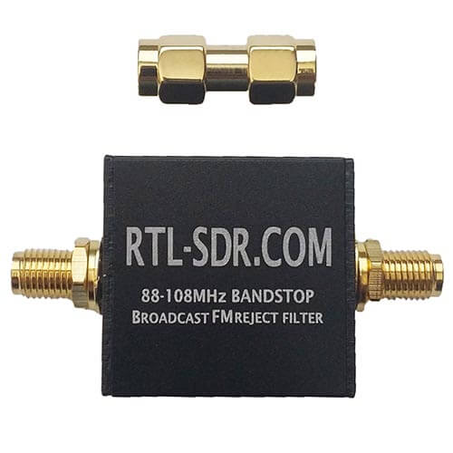
Thanks to PY2RAF for writing in and sharing some tests that he did on our RTL-SDR Blog BCFM bandstop filter. The RTL-SDR Blog filters were designed for RX purposes only, and no provisions were made for TX with only small SMD components being used. However PY2RAF wanted to test to see if the filter could at least handle 5W. The gist of his results is that the filter seems to handle 5W just fine, but as a precaution we wouldn’t recommend that anyone do this unless you really know what you are doing! 

As he does not have a blog, we present PY2RAF’s write up here:


Introduction

I am a Ham Radio Operator (PY2RAF), live in a metropolitan and very RF-polluted area.

Recently, I bought a handheld device and was back to the ether, after a 12-year hiatus. I assembled myself a 3-band quarter-wave “cat whisker” antenna for 144, 220 and 430 MHz (https://rf01.co/q/antena.jpg), calibrated it using a VNA and was quickly back up in the air.

Despite great and complimentary reports of good audio and transmission reports, my reception was sub-par: Lots of interference (QRM), static, squelch closing despite high S-bar signal.

I got intrigued by that, it just did not make sense: Had the VX-8 large mouth but bad ears? After a couple of days puzzled, I got a good idea: Put my RTL-SDR.com filter in the antenna.

The result was great: It immediately reduced the idle band noise from 6-7 S-bars to 3-4 S-bars. The squelched interrupted audio also stopped happening.

So, I could conclude that the strong FM BC band was overloading the receiving stage of the radio. Culprit found.

However, it brought another problem: the filter is NOT designed to cope with TX power (it is actually expressly stated at the product description page). However, the enhancement was just too good and I reached Carl asking about TX support or tests. Carl explained me that while the filter was not designed with TX power in mind, it withstand some minor current, because it supports Bias Tee currents.

I took it as a ‘good enough, I’ll test it’. See the results below.

Material

The Device Under Test (DUT) is a RTL-SDR.com FM Bandstop Filter. The transceiver is a Yaesu VX-8DR. I used a PocketVNA Vector Network Analyzer for checking the filter S21 characteristics and antenna S11 VSWR and impedance figures.  The realtime VSWR and TX power were monitored by a Diamond SX-200. I also used a Rtl-SDR.com SDR dongle and GQRX software to check for any transmission distortion. The radiant system (antenna) is a homebrew 3-band multiple dipole antenna, with VSWR < 1:1.3 in frequencies under test.

Method

Prior to any transmission, I put the DUT in the VNA and noted its frequency and attenuation figures.

Next step, assembled the test environment:

Transceiver – wattmeter – DUT – antenna.

I did then the first test: set the radio to its lowest power (0.05 W) and transmitted in frequency 144.320 MHz. I have also tuned the SDR dongle in the same frequency and watched the  waterfall pattern, while listening for the resulting audio. Then, repeated the very same test now adding the DUT before the antenna. The waterfall signature and the audio quality was pretty much the same and coherent. Transmitted for approx. 30 seconds using the Filter.

In the next step, I repeated the tests raising the TX power to 1W and 2.5W. I requested feedback from a fellow Ham operator and got report that the audio quality was pretty much the same with and without the filter, with no changes in RX S-units figures. It means, it did not distort the audio nor put significant attenuation into the signal.

The next test was the real world conditions test. I switched to the repeater 146.910 MHz, negative shift (actual TX 146.310, https://goo.gl/maps/45cUY58yot52). This repeater is located circa 100 KM north from my residence. After introducing myself to the repeater and stating the device test, I started transmitting first with a single watt: successfully hit the repeater. After around 7 comms averaging around 2 minutes, I asked for feedback with and without the filter: The reports that I have heard were of no change in the quality or fidelity of the transmission. The SWR was being continuously monitored by the Diamond SX-200, paying attention for any component disruption and sudden SWR raise: The operation was just normal. The filter also did not present any temperature change noticeable by touch.

Finally, I raised the TX power to 5W and requested report. I did a 1’30” TX and got report of normal transmission.

Results

This test validated, to me, the useful and robustness of the bandstop filter in my antenna as a permanent solution: It did not change the SWR figure, produced heating, noticeable attenuation or signal distortion: It became, since then, a permanent item between my radio and the antenna.

After the tests, I ran another round of DUT tests in VNA and the attenuation of the filter were the same as original: Working the way it should be.

Next day, I joined the repeater net again and spent around two hours ragchewing in the radio, accumulating something around 25 minutes of TX. Nothing wrong was noticed.

A Final Note

It is important to register that the DUT is working in a nicely matched (VSWR < 1:1.5) antenna system. Unmatched or higher VSWR figures can result in higher voltage, enough to break down the isolation. High-Q antenna systems might also present the same issue.
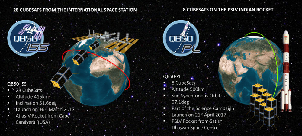
A Tour of Satellites in the QB50 Experiment

Over the last two weeks the QB50 experiment was launched from the International Space Station (ISS). The experiment consists of 36 cubesats built by various universities around the world, with the main science goal being to make measurements of the thermosphere (an upper atmospheric layer that the ISS orbits in). All the cubesats broadcast their telemetry in the 70cm (420 – 450 MHz) amateur band and they are expected to stay in orbit for about 3 months before falling back to earth. In a previous post we made a point to mention Lilacsat-1, which is one of the most interesting QB50 satellites due to its implementation of a FM to digital voice repeater on board.

The QB50 Experiment Launch

Over on his blog destevez has been following these satellites, and has uploaded a post that shows him receiving and decoding several of the satellite telemetry packets. His gr-satellites GNU Radio package provides a means to decode many of the satellites in the experiment.

Some packets from QB50 and other satellites in the 70cm amateur band.
Some packets from QB50 and other satellites received by destevez in the 70cm amateur band.

YouTube Video: A Tutorial on Receiving and Decoding NOAA and METEOR Satellites

Back in March we posted about The Thought Emporium’s YouTube video that explained weather satellites and demonstrated that images could be downloaded from them using an SDR like a HackRF or RTL-SDR. Now The Thought Emporium have uploaded part two of the video series, which is a tutorial that shows exactly how to use the free software to receive, demodulate and decode NOAA and Meteor satellites.

The first part of the video shows how to use SDR#, Audacity and WXtoIMG to receive NOAA APT weather images. The second part of the video shows how to use SDR#, Audacity, LRPTrx, LRPTofflinedecoder, SmoothMeteor and LRPT processor to receive Meteor M2 LRPT images.

Receiving Images From Satellites Part 2: Decoding and Demodulating NOAA and METEOR Transmissions

Signal Reverse Engineering Tool DSpectrum Upgraded to DSpectrumGUI

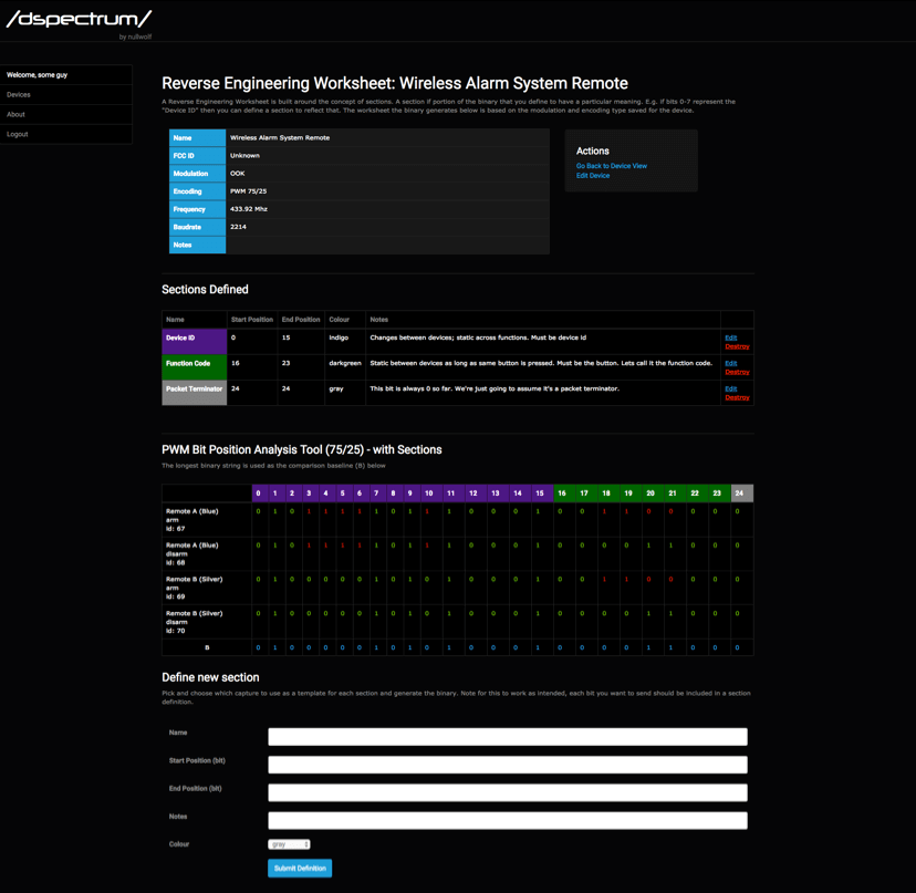
DSpectrum is a reverse engineering tool that aims to make it trivial to demodulate digital RF transmissions. It is built on top of the Inspectrum tool which makes it easy to visualize and manually turn a captured digital RF waveform into a string of bits for later analysis by providing a draggable visual overlay that helps with determining various digital signal properties. DSpectrum added features to Inspectrum like automatically converting the waveform into a binary string with thresholding. RF .wav files for these tools can be captured by any capable radio, such as an RTL-SDR or HackRF.

DSpectrum has recently been depreciated in favor of the new DSpectrumGUI which builds on the success of DSpectrum by providing a full interactive GUI that helps with the reverse engineering workflow. Some interesting new features include things like automatic analysis of the binary to determine the modulation and encoding types, the ability to submit/download reverse engineering worksheet templates to/from the community and binary generation for transmitting with a RFCat.

A similar tool is Universal Radio Hacker.

DSpectrumGUI
DSpectrumGUI

Detecting Pulsars with a Circularly Polarized Yagi and an RTL-SDR

Steve Olney VK2XV is the creator and administrator of the Neutron Star Group website which collects a listing of confirmed amateur attempts at pulsar detection, many of which have been made with a humble RTL-SDR dongle. A pulsar is a rotating neutron star that emits a beam of electromagnetic radiation. If this beam points towards the earth, it can then be observed with a large dish antenna and a radio, like the RTL-SDR.

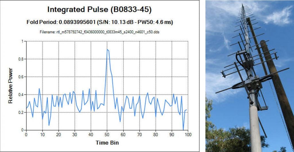
Now after more than four years of trying, Steve has finally been able make his own confirmed pulsar detection by using a 42-elment circularly polarized Yagi antenna tuned for 436 MHz and an RTL-SDR. Typically a large dish antenna is used to receive a pulsar, but Steve has instead used a fixed position circularly polarized Yagi antenna, which he writes has an equivalent aperture to a 2.8 meter diameter dish. His antenna can point directly upwards as his target is the Vela pulsar which happens to pass almost directly overhead at his location.

Detection of a pulsar involves determining its rotational period from the regular wideband noise pulses that they produce. Pulsar detections with large aperture dish antennas can easily be confirmed due to high SNR, but smaller weaker detectors require some use of some mathematical techniques to confirm a positive detection. This is especially important as it’s possible for terrestrial signals to mimic a pulsar. 

In order to detect and confirm the pulsar detection from a weak signal, Steve uses a technique called epoch folding, which makes use of the fact that the period of pulsar pulses are extremely regular. To verify the results he also makes use of techniques such as folding at the predicted period, de-dispersion and plotting daily results against the predicted results. These techniques are explained in more depth in his results post.

Steve's Results showing the detected pulsar period and his CP Yagi Antenna
Steve’s Results showing the detected pulsar period and his CP Yagi Antenna

Decoding the LilacSat-1 FM to Digital Voice Transponder

LilacSat-1 is an educational CubeSat built by students from the Harbin Institute of Technology (HIT) in China. It was recently launched from the ISS on 25 May 2017 as part of the QB50 science experiment to explore the lower thermosphere, and it is expected to stay in orbit for about 3 months. Apart from BPSK telemetry at 145.935 MHz, LilacSat-1 is interesting because it contains on board an FM to Codec2-BPSK digital voice amateur radio transponder at 145/436 MHz (uplink/downlink). It is probably the first amateur radio satellite to contain an FM to digital voice transponder.

To decode LilacSat-1 digital voice and telemetry you can use a Linux live CD provided by HIT, or download the GNU Radio decoder directly from the LilacSat-1 information page on the HIT website. The GNU Radio program can be used with any GNU Radio compatible SDR, such as an RTL-SDR.

Over on his blog, destevez has also created a lower latency digital voice decoder for LilacSat-1 that can found in the gr-satellites GNU Radio package, which contains decoders for multiple satellites as well. Destevez has also written about the Codec2 implementation used in LilacSat-1 in one of his previous posts.

An example of LilacSat-1 being decoded has also been uploaded by YouTube by Scott Chapman. In his test he used an RTL-SDR to work the pass live, but in the video shows an offline decoding received by his SDRplay which was also monitoring the same pass.

26 May 2017 LilacSat-1 First Try at Digital Repeater