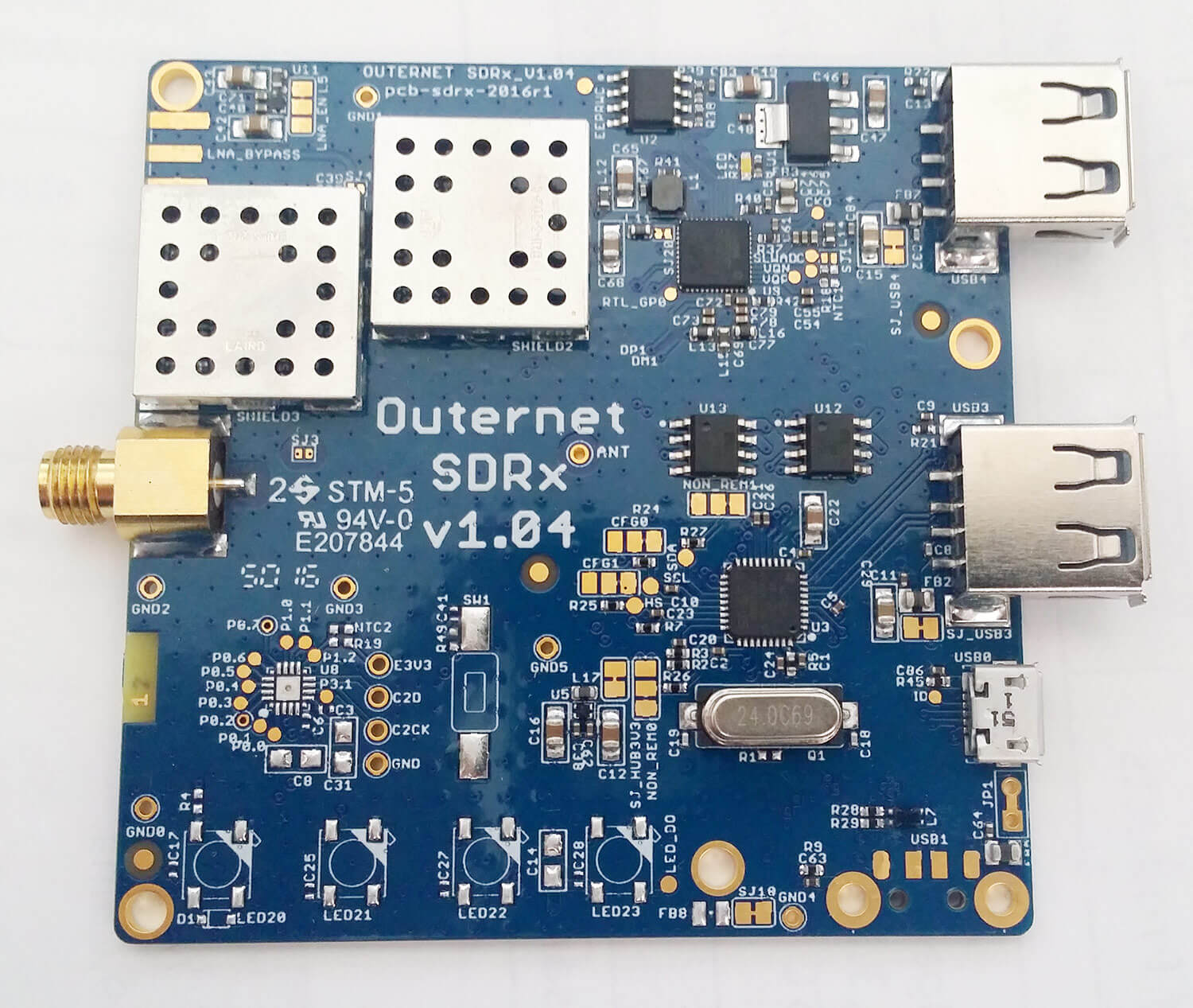
Recently the Outernet team sent us a prototype of their L-Band tuned RTL-SDR which is called the SDRx for testing. This is an RTL-SDR with RTL2832U and R820T2 chips together with an L-band LNA and filter on the same PCB. It is designed for their Outernet system which transmits from geostationary L-Band satellites.
Outernet is an L-band satellite service that hopes to be a library in the sky. Currently it is broadcasting down about 20 MB of data a day, with data like weather updates, books, pictures, wikipedia pages, APRS repeats and more.
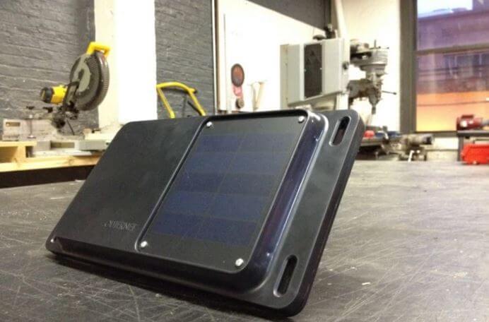
For their DIY Outernet kit they have been using E4000 or our RTL-SDR V3 dongles, so we speculate that this SDRx is going to be used in the “Lantern” which will be their fully assembled Outernet receiver product. The Lantern looks like it will be a single unit, with patch antenna, battery pack, solar panel, RTL-SDR radio and CHIP built into a plastic enclosure.
The upcoming RTL-SDR base Lantern Outernet Receiver.
The SDRx connects to the computer via a micro USB port. It also has a USB repeater and two USB expansion ports on board. This is useful as Outernet is designed to be used with the CHIP portable computer which only has one USB port. The expansion USB ports can be used for plugging in a portable hard drive which can be used as the storage for downloaded Outernet files.
We’ve been running a version of the SDRx prototype on an Outernet receiver for a number of weeks without issue. The SNR on Outernet signals is about identical to the V3 dongles combined with the external Outernet LNA and no L-band heat problems are observed.
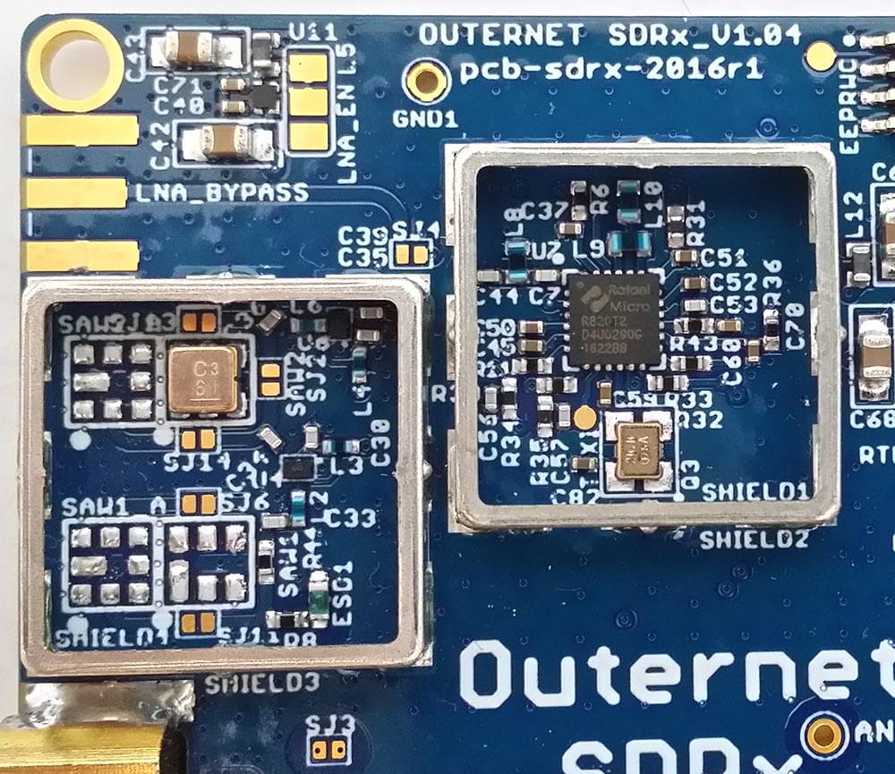
The SDRx PrototypeUnder the shield. SAW Filter, R820T2. LNA top left.
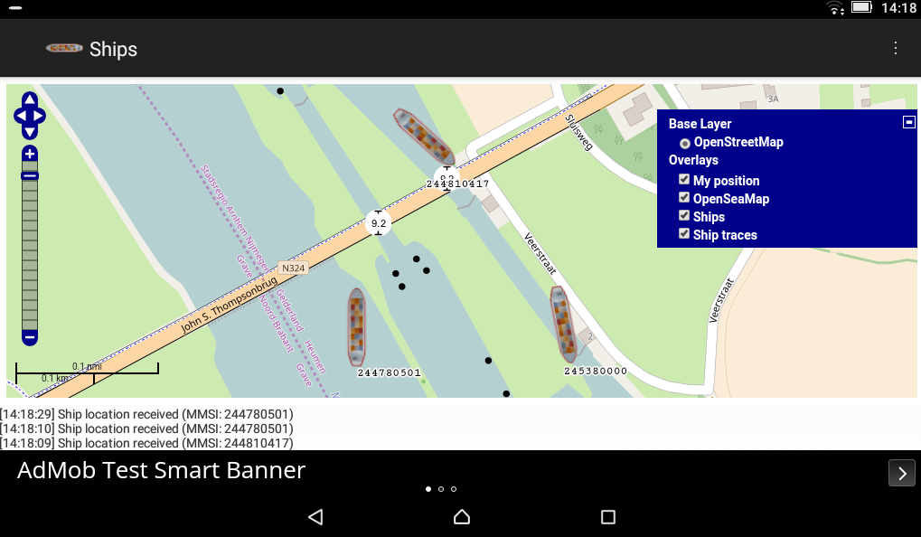
Ships also has another interesting feature which is that it will automatically determine the PPM offset of a dongle, meaning that generic dongles without TCXO’s can be easily used for AIS. It appears to do this by using the AIS signals themselves, so you will need sufficient AIS traffic in your area for the calibration to work.
AIS stands for Automatic Identification System, and is a system used to track the locations of marine vessels. It is similar to ADS-B in that nearby ships can be plotted and tracked on a map by using an RTL-SDR as the receiver. We have a tutorial for PC available here.
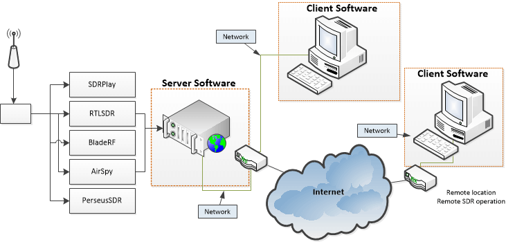
Cloud-SDR is a company that aims to make using SDR over the cloud/network/internet easier. It allows you to set up a remote SDR server that you can access from anywhere. Previously Cloud-SDR was still in development, but now we recently received mail from Cloud-SDR programmer Sylvain that the client and server software has just been released for the RTL-SDR. It appears that it also currently supports the Airspy, BladeRF, SDRplay and PerseusSDR.
The email reads:
I am pleased to inform you that we have just released two softwares compatible with your devices :
The Cloud-SDR free client, a windows + Linux (to be released soon) client able to run locally RTL-SDR devices (check the news/turorials, we have featured several times dongles from your blog)
The Cloud-SDR streaming server (codenamed SDRNode) , a windows + Linux (to be released soon) multi-user configurable streaming server.
SDRNode is a commercial software but an evaluation version is already available. Both softwares can be downloaded from our store after registration.
Source code for the drivers are already released as open source software through our GitHub repo: https://github.com/cloud-sdr
To download the software you must register an account with them at https://store.cloud-sdr.com/my-account. The client is free but the server costs 110 euros for personal and hobby usage, although a 30 day trial version is available. Currently only the Windows Client and Server are available, but they write that Linux should be available soon.
We tested the software out with an RTL-SDR V3. The client installation process was a simple wizard and after installation we launched the Cloud-SDR client by opening the shortcut “cSDRc” in the Start Menu. We found that the hardware needed to be plugged in first for the client to recognize it. The client is basic, but can already demodulate USB/LSB/CW/AM/FMN without trouble. It also has some interesting features:
Dual channel receiver: RXA and RXB are two totally independent receivers;
Geographic integration: Display on map beacons, ADS-B reported airliners, known HF broadcast stations or any geo-localized information coming from the SDRNode server;
GPS compatibility: plug a GPS receiver to your computer and track your location on the map, record signals with your position for later processing (coverage mapping etc.); display the UTC time;
Digital Terrain Elevation: See the terrain elevation around your position, or in the direction of the antenna directly on the map (requires to download the free SRTM3 files from NASA, with 90m resolution);
MP3 audio recording: record to mp3 the demodulated streams to reduce disk requirements;
Chat with other users connected to the SDRNode Group: when used as a remote client for the SDRNode streaming server, you can interact with other users with messages or station spotting;
Time-domain analysis: the MSR mode enables analysis of any sub-band and displays in real time the time domain signals of the selected spectrum portion. This sub-band can also be recorded (with geographic position if GPS is connected) and processed with provided MATLAB®.
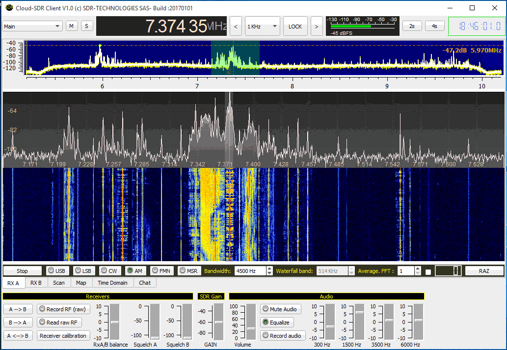
The Cloud-SDR Client Software
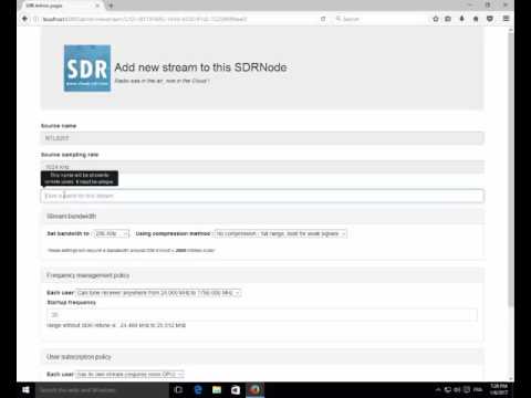
Next we tested the evaluation version of the SDR-Node server software on a remote laptop with an RTL-SDR connected. Again installation was easy, just follow the wizard after ordering the evaluation version. SDR-Node installs itself as a Windows service which starts up automatically on boot. To set up the Node we followed the guide shown in the video below. To connect with the client you need to know the IP address of the remote computer, the port is 8080, and the certificate is displayed on the server PC SDR-Node dashboard. We note that we also had to disable the Windows firewall to get it to connect, but it should be possible to also add SDR-Node to the firewall whitelist.
Using the SDRNode wizard
When streaming it appears that only 1/4 of the SDR sample rate can only be sent over the network. There are also compression options which can be used on slower networks or the internet to reduce bandwidth. Using the interface while in network mode was slightly laggy, but the waterfall and audio was smooth.
Overall everything worked as expected and it looks to be a very useful tool. More information is available at cloud-sdr.com. Some already existing alternative remote SDR streaming software that supports the RTL-SDR includes rtl_tcp, the SDR Console V2 server, OpenWebRX and ShinySDR.
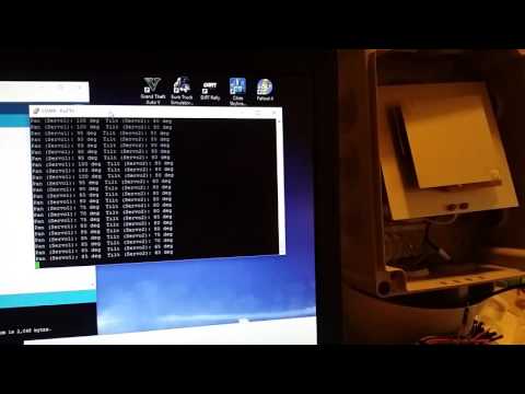
Over on YouTube user Tomi Simola has uploaded a video showing his servo based Outernet satellite antenna tracker. Outernet uses L-band geostationary satellites which means that they are at a fixed position in the sky. Optimal reception of the Outernet and other L-Band satellite signals can be obtained by pointing the patch antenna towards the satellite.
Tomi wanted an easy way to remotely switch the antenna to point at one of two geostationary satellites, Alphasat at 25E which has the Outernet signal and Inmarsat at 64E which has more services like AERO and STD-C. Another potential use of his tracker might be for tracking L-Band satellite while in a moving vehicle such as a car or boat.
To automatically point the Outernet L-band patch antenna Tomi used a commonly found Pan-Tilt servo mounted inside an waterproof enclosure. On the servo is a 3D printed mount which the patch antenna is attached on. An Arduino Nano with Bluetooth module allows control of the servo.
A downconverter is a circuit that allows the RTL-SDR to receive frequencies above its maximum frequency range of about 1.8 GHz. It works by converting all higher frequencies down into a lower frequency which can be received by the RTL-SDR. It is the opposite of an upconverter which is used to receive HF frequencies on an RTL-SDR. In the past the Outernet project was working on a commercial downconverter product for the RTL-SDR, but they had to unfortunately put an end to that project as the costs were not economical.
But now over on GitHub Raziel Einhorn has uploaded plans for his open hardware 1.5 – 3 GHz downconverter which is code named Nigun (Melody). Currently the design has just about been completed, and he is planning to order the first prototype this January. The main component appears to be the ADRF6612 RF mixer which is controlled by an ATSAMD21E18A ARM microcontroller. On the GitHub page he explains the main properties as:
Dynamic LO – LO will be determined by the user and programmed by the MCU
Almost no filtering – will leave this challenge outside of this project scope
Power up and programming via micro-usb connector. Should be able to power up from a USB power-pack (but probably not from a computer port)
Highest RF frequency will be 3GHz
Product also features a VCO for signal-generation purposes. VCO support should be 200-2700MHz
The beta 2.75 version of HDSDR was released about two months ago. Now the stable version has just been released. HDSDR is a free general purpose SDR receiver, similar in nature to other programs like SDR# and SDR-Console. HDSDR can be downloaded from hdsdr.de.
The author of HDSDR emailed us with the following release information:
this morning we released the final version 2.75. Here’s the changelog:
Version 2.75 (January 01, 2017) – more recording options – support for 8bit sampling format – ideal for RTLSDR, halving RF recording size – display level / clipping for RF and AF – additive noise generator for hiding aliases – Highpass Filter for AM/FM deactivatable – useful for slow digimodes – configurable gain for I/Q output – useful for digimode decoding weak signals of SDRs with >16 Bit dynamic range – Uniform “Calibration” dialog for Frequency/S-Meter/DC Removal/Channel Skew – “Custom color palette” to customize colors of Waterfall/Spectrum and some more – output soundcard no longer necessary (e.g. for recording or monitoring) – support for 8k display resolution (7680×4320) – some new keyboard shortcuts (see ) – extended ExtIO capabilities – experimental transmit capability through ExtIO API interface – many fixes and improvements
Some of the new features were introduced especially for the RTLSDR Dongles:
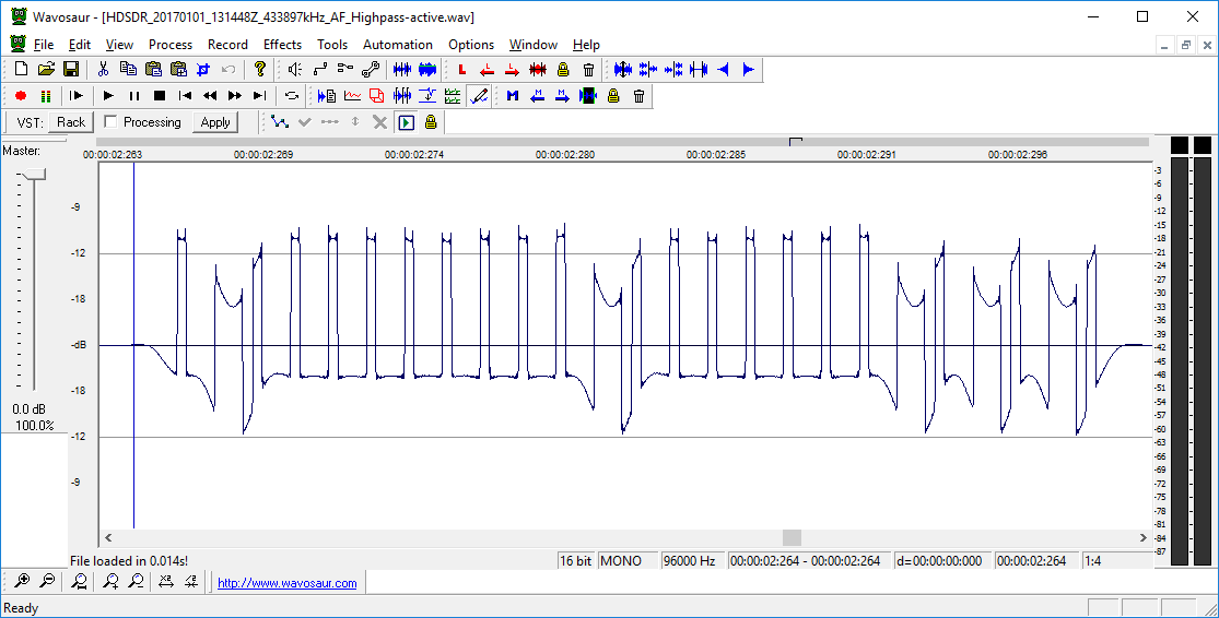
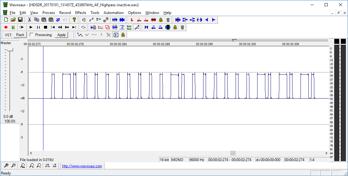
Especially for decoding this kind of signals (AM/FM) , deactivating the Highpass filter (Ctrl-H) will make the demodulated Audio clearer: long periods of positive or negative levels will not fade towards zero. Find attached recordings and screenshots with active and deactivated highpass filter of a garage door opener demodulated in AM.
– additive noise generator (Ctrl-N) is for hiding some alias carriers in scenarios where the ADC does not see real noise from the antenna. The noise generators level has to be configured carefully for not hiding real signals. A level between -25 to -10 looked fine for me. But that should be measured in a lab.
Below are the mentioned attached images and .wav files.
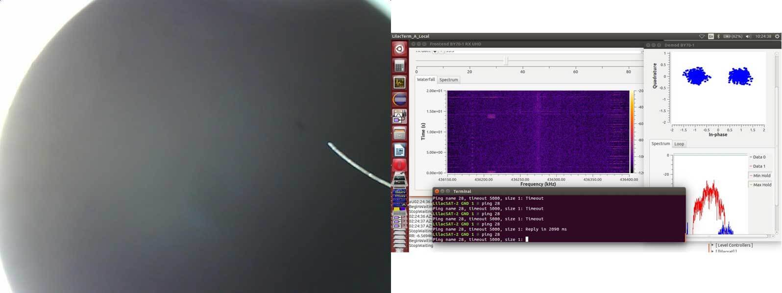
BY70-1 is a Chinese amateur Cubesat satellite which was recently launched on December 29, 2016. It is expected to stay in orbit for only 1 – 2 months due to a partial failure with the satellite releasing into an incorrect orbit. The purpose of the satellite is for education in schools and for amateur radio use. The receivable signals include an FM repeater and BPSK telemetry beacon both of which can be received at 436.2 MHz. The telemetry beacon is interesting because it also transmits images from an on board visible light camera. These signals can easily be received with an RTL-SDR or other SDR with an appropriate antenna.
Over on his blog Daneil Estevez has been posting about decoding these telemetry images. He’s been using telemetry data collected by other listeners, and the gr-satellites GNU Radio decoder which is capable of decoding the telemetry beacons on many amateur radio satellites. So far the decoded images haven’t been great, they’re just mostly black with nothing really discernible. Hopefully future decodes will show better images.
If you want to track the satellite and attempt a decode, the Satellite AR Android app has the satellite in its database.
Not many people seem to have gotten telemetry decodes or images yet, but below we show an image decoded by @bg2bhc on Twitter.
Vivaldi’s are linearly polarized broadband antennas that have a directional radiation pattern at higher frequencies. The high end SDR manufacturer RF Space produces their own Vivaldi antennas made from PCB boards which they sell online. The larger the antenna, the lower its receiving frequency, and ones that go down to about 200 MHz are almost the size of a full adult person. But all sizes receive up to 6 GHz maximum. Typically smaller versions of Vivald antennas have been used in the past for L-Band satellite reception.
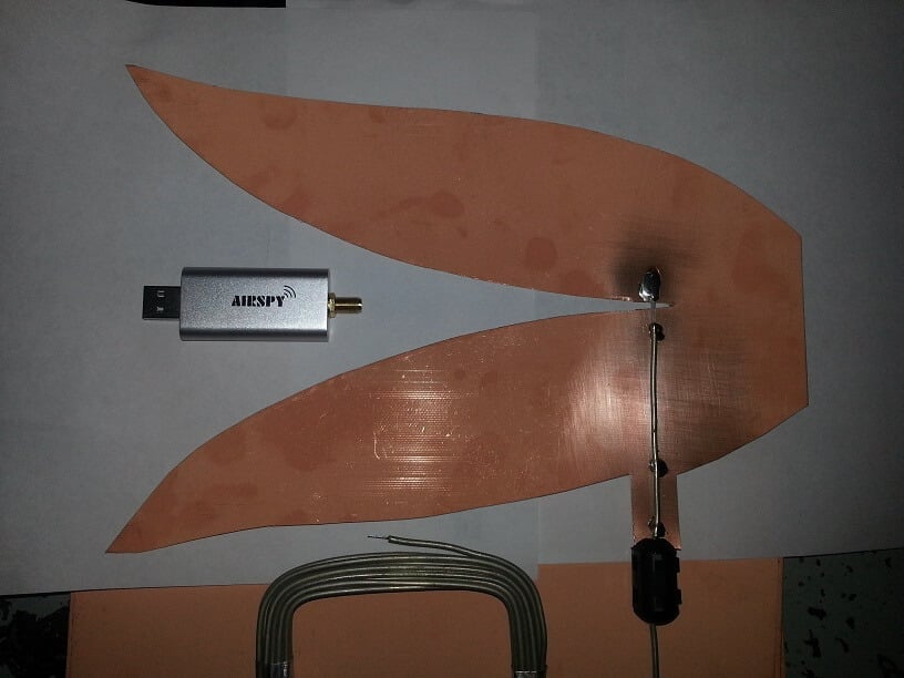
Over on his blog KD0CQ noted that he always had trouble trying to purchase a Vivaldi from RF Space because they were too popular and always out of stock. So he decided to try and build his own out of PCB boards. On this page he’s collected a bunch of Vivaldi cutout or transfer images. On his second page he shows a Vivaldi antenna that he built out of PCB material, just by using scissors and semi-rigid coax. With the Vivaldi placed outdoors he’s been able to successfully receive and decode L-Band AERO on his Airspy Mini even without an LNA.
KD0CQ writes that he’ll update his blog soon with more results.
Simple Vivaldi antenna by KD0CQ cut out of PCB board.