Tagged: rtl-sdr

SMOG-1 PocketQube Satellite Successfully Launched and in Orbit

Thank you to Zoltan Doczi (HA7DCD) for submitting news about the successful launch and first reception of the SMOG-1 PocketQube Satellite (which is only 5x5x5cm in size). The pre-launch press release by Tech University of Budapest is available here, and the SMOG-1 Facebook page provided additional updates.

Back in April 2020 we first heard about the launch of SMOG-P which was the first functioning 1-PocketQube satellite, and was designed to measure electromagnetic pollution (electrosmog) from space. SMOG-1 is the successor to SMOG-P and it carries a similar mission to measure electromagnetic pollution generated by human activity in space around the Earth. Interestingly it also carries a magnetically lossy material under it's solar panels which is to act as a brake, reducing the 18-25 Orbital lifespan, thus reducing space trash after the primary mission is complete.

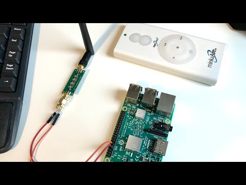
According to the receive and decoding instructions provided by Levente Dudas, SMOG-1 can be received with a simple satellite antennas, such as a handheld Yagi, Turnstile, Dipole or quadrifilar-helix antenna. The telemetry frequency is 437.345 MHz with callsign HA5BME. For the radio an RTL-SDR connected to a Raspberry Pi can be used, and the telemetry decoding software can be found on GitLab

SMOG-1 can be tracked here, although Zoltan mentions that the TLEs may not yet be accurate for several more days or weeks, as was seen with the launch of SMOG-P as well. The reason is that it is difficult for the NORAD radars to see these tiny PockQube satellites which is required for TLE generation.

Preorder Sale: Active L-Band 1525-1660 Inmarsat and Iridium Patch Back In Stock for $44.95

We have just received stock of our new L-band active patch antenna design. The antenna is designed for receiving RHCP L-band satellites such as Inmarsat, Iridium, GPS and other satellites that transmit between 1525 - 1660 MHz (please note that you cannot use it for weak signals that require a dish like HRPT or GOES). The antenna comes as a set with a large suction cup, 3M RG174 extension cable and bendable tripod to help with mounting. Preorder pricing is US$44.95 including free worldwide shipping to most countries shipped from our warehouse in Shanghai. At the end of this week (extended for one more week!) pricing will rise to the standard cost of US$49.95. Amazon stock will require time, and won't be in for at least 6+ weeks.

Please see our store to order the unit

Like our previous patch design, this is an actively amplified antenna as it contains a built in low noise amplifier which takes power from a 3.3 - 5V bias tee. This power is available from from our RTL-SDR Blog V3 dongles, and other SDRs like the Airspy, HackRF and SDRplay. It also has a built in SAW filter after the LNA to help reduce terrestrial interference.

Compared to the previous design the new patch is larger (175 x 175 mm) with higher gain and wider radiation pattern. This allows for much easier pointing of the antenna and for much stronger signals. The upper frequency range has also been extended to 1660 MHz from 1625 MHz. The included suction cup is also much larger allowing for the patch to point at more angles without being restricted by the window. The patch is enclosed within a new weatherproof plastic enclosure. 

L-Band Patch with Accessories
L-Band Patch Mounting Examples

The screenshots below show the patch receiving various signals like AERO, STD-C and Iridium

Inmarsat Reception
Inmarsat Reception
Airspy Showing Patch Bandwidth
GPS "hump" visible

Usage Tips

  • The antenna should be used with one meter or more of coax cable. It may perform poorly if the RTL-SDR is placed right at the antenna due to interference. If you want to run very long cable, then low loss coax should be used. 
  • The patch can be used flat, or angled towards the satellite. Angling it towards the satellite will yield significantly higher gain.
  • If you have very strong cell phone interference in your area, try using the patch a bit lower to the ground, and use buildings to block the interfering signal.
  • If you want to mount this on a car roof, you can use a standard mag-mount camera adapter.
  • When using the suction cup, ensure you wipe down the cup and the window surface before sticking it on. Have a backup plan in case the suction fails.

What can you do with this antenna?

Project Horus 55: Live Video from a High Altitude Balloon

Project Horus 55 was a project that involved creating a high altitude balloon with payload that could broadcast live video down to ground station observers, as well as creating the ground station receive hardware. On March 7th 2021 the balloon was launched and ground station observers successfully received the live video.

The transmission hardware onboard the balloon was a Raspberry Pi Zero which captured and compressed the video, and a LimeSDR Mini which broadcast a DVB-S signal at 445 MHz. Power amplification was provided by an 800mW LDMOS amplifier. On the ground station side, RTL-SDRs were used as the receiving hardware and SDRAngel as the software. Although high gain auto tracking Yagi's were used by the main ground station team, it's interesting to note that the balloon chase team were also able to receive the video with a simple vechicle mounted turnstile.

In the video below Mark VK5QI who was one of the people behind the project discusses the setup before the launch.

Live Amateur TV from 100,000 feet!

The video below shows the launch and some of the live video received.

GPU Accelerated RTL-SDR Radio Interferometer Code For Radio Astronomy

Evan Mayer (@millijanskys) has recently released some code called “effex” that allows you to use two RTL-SDR dongles as an interferometer for radio astronomy and other experiments.

The hardware used is two RTL-SDR Blog V3 dongles with synchronized oscillators via the selectable clock headers, two 1420 MHz filtered LNAs, a splitter and noise source consisting of a 50 Ohm load and wideband LNA, and a NVIDIA Jetson Nano GPU single board computer. We note that Evans code should also run on our KerberosSDR with some modifications to enable the built in noise source during calibration.

To add to this Evan wrote to us explaining how this code might be used:

You could start to do some basic interferometric imaging by adding more coherent channels. This is exactly what Daniel Estévez just did with USRPs and GNU Radio at the Allen Telescope Array.

Did you see the “picture” of the supermassive black hole shadow released by the Event Horizon Telescope collaboration in 2019? The “ring of fire” or “donut” image? Daniel’s image and that image were created by “aperture synthesis.”

In aperture synthesis, the signals from each pair of antennas distributed across an area can be cross-correlated to measure one component of the 2D Fourier transform of the radio brightness distribution on the sky. But, you need coherent receivers (or REALLY good time stamps) to cross-correlate the signals from the antennas. Get enough pairs of antennas, and you can start to more fully sample the 2D Fourier space of the sky brightness distribution, which you can then use to reconstruct a real image.

This is how distributed radio arrays like the EHT work, as well as localized ones like ALMA or LOFAR.

Frugal Radio: Monitoring VHF Airband Aviation Frequencies at the Airport

Rob from Frugal Radio has recently uploaded the next video in his airband monitoring series. In this video Rob explains various airband communications that can be received from the airport, and explains about needing to be in the line of sight of an airport in order to receive them.

He goes on to explain signals and airport radio communications channels such as ATIS, Clearance Delivery, Tower, Arrivals (Approach), Departures, Radar and Terminal communications. The video provides various examples of these communications being received with an SDRplay software defined radio.

Monitoring VHF Airband Aviation Frequencies at the Airport

GNU Radio Amateur Radio Meeting: A Look at Project 25 (P25) Digital Radio

Over on their YouTube channel GNU Radio have uploaded a recent talk by Aaron Rossetto titled "A Look at Project 25 (P25) Digital Radio". The talk explains the North American public safety P25 system in great depth, and is a good watch for anyone looking into details on how the system works in a deeply technical way. He later shows some examples of his P25 decoding and recording setup. Slides can be found here, and the video is posted below.

Agenda: In this presentation, I will introduce Project 25 digital radio, with a strong emphasis on its use in North American public safety trunked radio systems, and to describe experiments monitoring and decoding P25 traffic using GNU Radio code.

  • What is Project 25?
  • A brief introduction to trunked radio
  • Diving into the P25 protocol
    • Modulation
    • Packet framing and encapsulation
    • Packet types
  • GNU Radio and P25 decoding experiments
Amateur Radio Meetup: P25 Trunked Radio

Receiving Shortwave Radiograms with an RTL-SDR and MultiPSK

Shortwave Radiogram's are digital broadcasts of images, text and sometimes HTML files that are regularly broadcast on two shortwave radio stations, WRMI in Florida and WINB in Pennsylvania. The transmissions are produced and presented by Dr. Kim Andrew Elliott, and a schedule can be found on the Shortwave Radiogram website.

Over on his blog Jeremy Clark has been experimenting with receiving shortwave radiograms with an RTL-SDR and upconverter. To do this he notes the transmission schedule on the shortwave radiogram website, and uses SDR# and MultiPSK in MFSK mode to receive and decode the data. Jeremy's post explains the MFSK transmission mode and shows a few examples of radiograms that he's received including a video posted below showing live reception and decoding.

RTL-SDR for Shortwave Radiogram

Controlling a Wireless Ceiling Fan with an RTL-SDR and RPiTX on a Raspberry Pi

Over on YouTube River's Educational Channel has uploaded a new video showing how he uses a Raspberry Pi to control a ceiling fan via it's wireless control signal. Back in January we posted about River's first video where he shows him using and RTL-SDR and Universal Radio Hacker (URH) to reverse engineer the control signal.

In this new video River uses the RPiTX software to generate the control signal without requiring any additional transmit hardware. He first explains how RPiTX can generate an arbitrary signal from a square wave and talks a bit about the harmonics this creates. To reduce harmonics he adds a simple low pass filter to the GPIO output.

Next to control the fan he uses the "sendook" program that is included with RPiTX to transmit the binary control string that he reverse engineered in his original video. Finally he creates a simple web server so that he can control his ceiling fans via his phone and integrate it into his smart home.

Abusing Raspberry Pi GPIO pins as a radio transmitter to control my ceiling fan