Tagged: rtl-sdr

In Testing: Customized Drivers for RTL-SDR Blog V3 SDRs

We've recently released a modified version of the Osmocom RTL-SDR drivers that has a few enhancements particularly for RTL-SDR Blog V3 units. The changes merge improvements to L-Band PLL locking performance which may be necessary for operating units in high ambient heat environments and the RTL_TCP performance enhancements by Stephen Blinick.

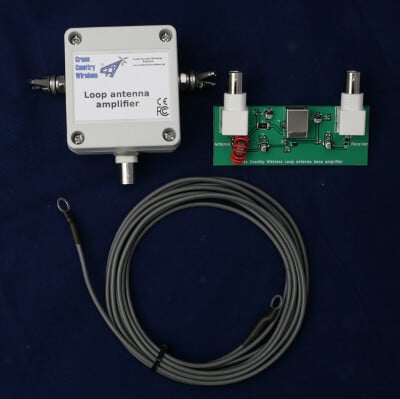
If you want to toggle the bias tee ON/OFF in SDR#, we've also made use of the "Offset Tuning" checkbox in the RTL-SDR settings. This checkbox is unused for R820T2 RTL-SDRs, so we've added code that will toggle the bias tee ON/OFF with this checkbox. 

In addition we've also made use of some unused EEPROM flags to create a method that allows you to force the bias tee to be always ON if a certain EEPROM flag is set. You can also force direct sampling mode with another EEPROM flag. Note that these force flags will only work if you are using these drivers.

A Windows release is available on the Github Releases. To use with SDR#, simply replace the rtlsdr.dll file in the SDR# folder with the one in the Release.zip file. To install on Linux, follow the instructions in the Readme, and remember to follow the instructions to remove librtlsdr-dev if you previously installed drivers via the package manager.

If there are any problems or feedback, please open an issue on GitHub. List of changes shown below.

1) VCO PLL current fix - Improves stability at frequencies above ~1.5 GHz https://www.rtl-sdr.com/beta-testing-a-modified-rtl-sdr-driver-for-l-band-heat-issues/

2) RTL_TCP ring buffer enhancement by Stephen Blinick https://www.rtl-sdr.com/significantly-improving-rtl_tcps-performance-with-ring-buffers/

3) Enabled direct sampling for rtl_tcp

4) rtl_biast program added, including the ability to turn on/off any GPIO

5) Hack to force the bias tee to always be on by setting the unused IR endpoint bit to 0 in the EEPROM. Example to force the BT to be always ON "rtl_eeprom -b y", to remove forced BT "rtl_eeprom -b n"

6) Hack to force direct sampling to be always on by setting the unused remote-enabled bit to 1 in the EEPROM. Example to force direct samping always "rtl_eeprom -q y". To remove forced direct sampling "rtl_eeprom -q n"

7) Repurposed "offset tuning" to toggle bias tee ON/OFF. We can now use the "offset tuning" button in SDR# and other programs to toggle the bias tee if there is no specific button in the GUI.

Dash Mounted ADS-B With an RTL-SDR Blog V3

Reddit user [Bobcalamarie] recently [posted] about how he uses his car dash mounted Android tablet along with an RTL-SDR Blog V3 and a magnetic mount antenna while sitting in traffic to track aircraft overhead.

We’ve seen something similar to this once before when [Signals Everywhere] uploaded a video showing off ADS-B reception (among other things) to a dash-mounted Windows tablet and an Android head unit.

The software used by Bobcalamarie is the Android [Avare ADS-B] software which can be found in the Google Play Store. However, other applications exist for Windows, Linux, and other operating systems as well. Some software such as [Virtual Radar Server] even allows you to set-up alerts for specific types of aircraft. Which while we wouldn’t condone it, it might come in handy for someone in traffic.

What would you do if you had an SDR installed in your vehicle? We would love to hear what you have to say in the comments below.

Dash Mounted ADS-B Reception

ORBCOMM Receiver: New Open Source Software for Monitoring Orbcomm Satellites

Thank you to Frank for submitting his new RTL-SDR compatible Orbcomm Satellite monitor software called "Orbcomm Receiver". Orbcomm is a low earth orbit satellite communications system that operates in the 137 - 138 MHz frequency range. The satellites specialize in remote IoT and machine to machine (M2M) connectivity, an example use case being a GPS tracker on a shipping container regularly uploading GPS coordinates from anywhere in the world via the Orbcomm satellites. Orbcomm satellite signals are fairly strong and can easily be received with an RTL-SDR and V-Dipole antenna.

We haven't posted about Orbcomm on this blog since 2015 since there is not many interesting things to say about it. The data is all encrypted, and the only information you can really see is Orbcomm satellite ID, frequency and positioning data. Franks software doesn't change this fact, but his software is all open source, so it may be a useful tool for learning about satellite signal DSP processing. Frank writes:

There are a couple different projects out there to decode ORBCOMM signals (Orbcomm-Plotter and MultiPSK). What makes my project different from these is that I wrote it as a learning project. So all of the signal processing, written in Python, is available to the user and is decently documented. I hope this can be a good learning resource for people who want to see a practical example of satellite communications signal processing. Also, my software is open source and free to use.

Currently, the software can do offline or real-time decoding of a single ORBCOMM downlink channel. The transmitted bits of the ORBCOMM signal are demodulated and when the packet type is known, the packet information is decoded. There are a lot of ORBCOMM packets that can't be decoded and of course the message data is encrypted so that information is not available. But, there is still a ton of interesting information available.

The project is still in development so it has some limitations. For real-time recordings, I only support RTLSDRs currently. Also, I'm having trouble getting the real-time processing to work on mac OS, so currently that mode is only supported on linux. However, I have included a couple data files in the repo, so even without an SDR, users can experiment with the signal processing. I welcome any bug reports or suggestions.

Orbcomm Packet Decoding. Showing Realtime Satellite Position.

r2Cloud: Software for Automatically Decoding APT/LRPT Weather Satellites and Cubesats on a Raspberry Pi with RTL-SDR

Thanks to a tweet by @rf_hacking we recently came across an interesting project called "r2cloud". This is an open source program provided on a ready to use image for the Raspberry Pi that can be used to set up an automated satellite recording station for NOAA APT and Meteor LRPT signals, as well as for CubeSats.

The software presents a web based user interface that is easy to setup and view decoded images on. It appears that the software also communicates with a public server that can aggregate and log your data, and also provide it to SatNOGS and provide FunCube satellite telemetry to FunCube Warehouse.

Block Diagram for the r2cloud software.

A Motorized Backyard Radio Astronomy Telescope made with an RTL-SDR

A Geostationary Satellite Imaged with the RTL-SDR Based Mini Radio Telescope

Just a few days we posted an update on the PICTOR open source radio telescope project. That project makes use of an RTL-SDR and a small dish antenna to receive the Hydrogen line, and is able to measure properties of our galaxy such as determining the shape of our galaxy.

Now over on Hackaday another amateur radio telescope project has been posted, this one called the "Mini Radio Telescope" (MRT) which was made by Professor James Aguirre of the University of Pennsylvania. This project makes use of a spare Direct TV satellite dish and an RTL-SDR to make radio astronomy observations. What makes this project interesting in particular is the automatic pan and tilt rotor that is part of the design. Unlike other amateur radio telescopes, this motorized design can track the sky, and map it over time. This allows you to create actual radio images of the sky. The image on the right shows a geostationary satellite imaged with the dish.

In the past we saw a similar project by the Thought Emporium YouTube channel which used a tracking mount and a HackRF to generate images of the WiFi spectrum. This was to be a precursor to a motorized tracking mount for radio astronomy but it doesn't seem that they completed that project yet.

Professor James Aguirre 's project including designs for the rotor is fully open source and can be found over on GitHub.

The Miniature Radio Telescope Setup

An Active Low Cost HF Loop Antenna Made in the UK

Cross Country Wireless is a UK based company that has created an active HF loop antenna for only $70 USD including international shipping. The loop appears to have already been for sale for a while now, but recently they've created a new version that can be easily powered by a 5V bias tee with at least a 67 mA current capacity. This makes it very easy to use with radios that have built in bias tee's such as our RTL-SDR Blog V3 and SDRplay and Airspy units. The page reads:

The Loop Antenna Amplifier contains all the electronics needed for home DIY construction of an active loop (magnetic loop) low noise receiving antenna.

The amplifier consists of two units, a weatherproofed outdoor unit for connection to a suitable loop and a base unit to further amplify the signal and to provide DC power up the coaxial cable to the outdoor unit.

The outdoor unit is housed in a polycarbonate box with stainless steel antenna connections and a BNC socket. The indoor unit is a PCB with two BNC connectors and a USB socket to take 5V from a USB socket on a PC or phone charger.

Like our other active antenna products it has RF overload protection to allow it to be used very close to transmit antennas without damaging the amplifier or the attached receiver.

The loop depends on what the user has available. We have tested it with simple wire loops or deltas, coax loops and an alloy loop made from a bicycle wheel rim. We supply a 3m (10 ft) length of wire as a simple loop to make a first loop for testing.

The photograph on the right shows the prototype with a 1m diameter loop of LDF4-50 coax cable as a test loop.

With a simple wire loop or delta and a small USB powerbank it makes a very compact and portable receiving antenna for holiday listening or covert use.

The latest version can now have the head unit powered directly from receivers with a 5V bias-tee such as the SDRplay receivers or some RTL-SDR dongle receivers with a bias-tee option.

Specifications:

  • Frequency range: 10 kHz to 30 MHz
  • Loop amplifier input impedance: 0.3 ohms
  • Output impedance: 50 ohms
  • Supply voltage: 5 V from USB socket or charger
  • Supply current (head and base unit): 112 mA
  • Supply current (head unit fed with 5V bias-tee): 67 mA
  • Loop antenna outdoor unit connectors: Two M6 stainless steel threaded studs and BNC female (RF out 50 ohms)

There is no comparison yet that we've seen on how this loop compares against the cheaper US$45 Chinese made MLA-30 loop. In a previous post Martin (G8JNJ) reviewed the MLA-30 and noted several design flaws after reverse engineering the circuit. He has let us know that he will also be reviewing the Cross Country Wireless Active Loop and will let us know his thoughts in the future.

Cross Country Wireless Loop
Cross Country Wireless Loop Antenna Amplifier VLF test with 1m diameter coax loop

Updates on the PICTOR Low Cost Open Source Radio Telescope Based on RTL-SDR

Back in July we posted about PICTOR, an open source and RTL-SDR based radio telescope project. The owner of the project recently wrote in and wanted to share some updates. His text is below:

A few months ago, PICTOR was launched. PICTOR is a free to use open source radio telescope that allows anyone to observe the sky in the 1300~1700 MHz range at any time via the easy-to-use online platform.

The goal of this effort is to introduce students, educators, astronomers and others to the majesty of the radio sky, promoting radio astronomy education, without the need of building a large and expensive radio telescope. 

Since the initial launch, PICTOR has gotten lots of updates and improvements, particularly in the software backend, providing more data to the users, using advanced techniques to increase the signal-to-noise ratio by calibrating spectra and mitigating radio frequency interference (RFI) (if present).

Here is an example observation with PICTOR, clearly showing the detection of 3 hydrogen-dense regions corresponding to 3 unique spiral arms in the Milky Way!

Graphs from the PICTOR RTL-SDR Radio Telescope showing the 3 unique spiral arms in the Milky Way.

If you’re new to radio-astronomy, the developer of PICTOR has provided a PDF including some introductory radio astronomy information and instructions on how to observe the radio sky with PICTOR: https://www.pictortelescope.com/Observing_the_radio_sky_with_PICTOR.pdf

Using an RTL-SDR to Investigate GPS Interference Problems on Drones Caused By HD Cameras

Over on YouTube Drone and Model Aircraft enthusiast channel Paweł Spychalski has uploaded a video showing how he determined that cheap HD cameras that are commonly used on hobbyist drones can cause locking issues with the on board GPS. He writes:

You might believe it or not (today I will prove it, however) that HD cameras, especially cheap ones, can be responsible for GPS problems on your drones and model airplanes. The majority of HD cameras (RunCam Split, Runcam Split Mini, Foxeer Mix, Caddx Tarsier) generate RF noise on different frequencies. Some of them on 433MHz, some on 900MHz, but most of them also at around 1GHz. Just where one of the frequencies used by GPS signal sits. As a result, many GPS modules are reported to have problems getting a fix when the HD camera is running.

In the video he uses an RTL-SDR and SDR# to demonstrate the interference that shows up when a cheap HD camera is turned on. He shows how the interference is present at almost all frequencies from the ISM band frequencies commonly used for control and telemetry to the 1.5 GHz GPS frequencies.

GPS vs HD cameras - it's all about RF noise