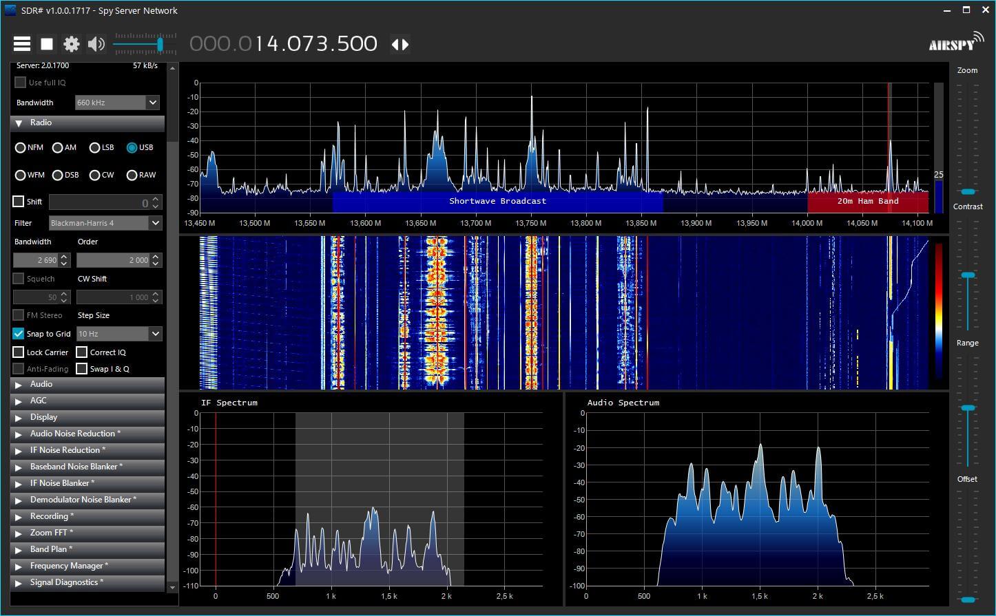
We are pleased to announce the release of SDR# r1717 with the Telerik User Interface.
This is quite a big jump from the old UI components that will allow us to add many fancy features in the upcoming revisions. For now, the functionality of the software was ported "one to one" with full support of the existing plugins. A new Plugin API for the tool bar was added which allows plugin developers to add/remove special buttons for quick access.
Despite a slightly longer loading time at the startup of the application, many performance improvements should be noticed in run time, especially the CPU usage. The package is now distributed with a set of skins/themes you can select in the control panel under "Display". Later on, we will add custom skins loading capability so you can customize the look and feel of the whole program.
Please note that some themes have slower rendering than others. You will have to experiment until you settle with something that is acceptable for the eye candy and the CPU usage / UI reactivity.
Some older plugins may not support the "Dark" themes and will have some rendering problems. The last unskinned version of SDR# will be still available for download in case you really need it. In any case, plugin developers are invited to support the new skins by either using Telerik UI components or at least setting the display properties of the old components so they render properly.
Last month we posted a collection of reviews about the MLA-30 which is a budget magnetic loop antenna designed for receiving HF signals. The overall consensus from the reviews was that it worked decently for the price, but of course could never live up to the high end loops that cost hundreds of dollars.
Recently Martin (G8JNJ) reverse engineered the active circuit used on the loop from photos taken by M0LMK and has made some observations on it's performance, noting that it's design isn't very good. First he notes that the amplifier chip is a Texas TL592B two stage video amplifier which isn't that great for this application. His measurements show an OIP3 of 20dBm, a P1 saturation of -3dBm and a noise figure of 12dB.
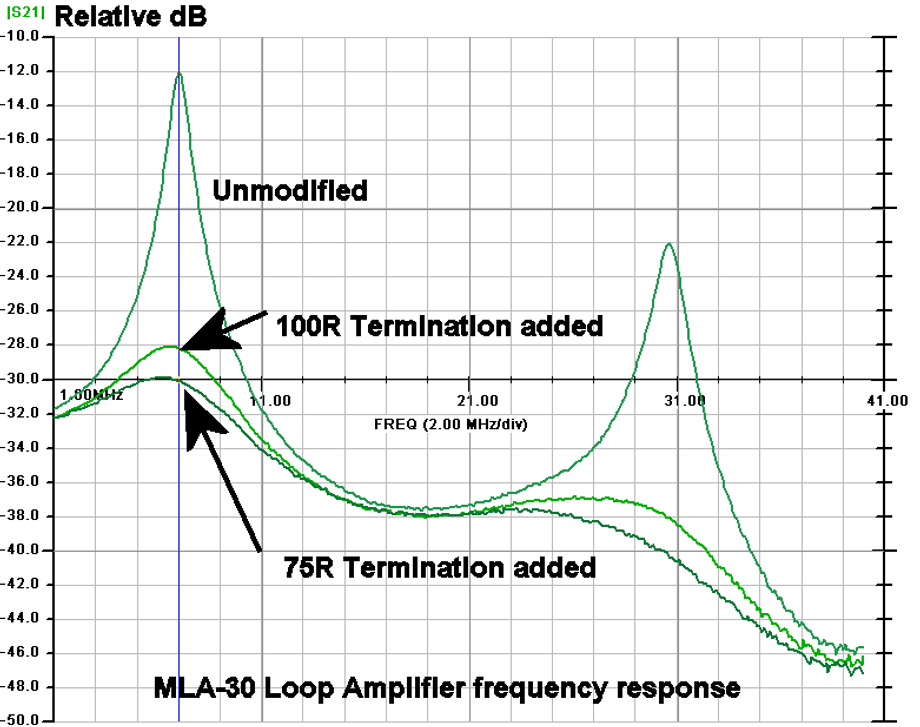
Of interest, he explains that the creator of this loop has designed it poorly as the impedance match of the loop to low pass filter is very wrong, resulting in a very poor amplitude/frequency response. He shows how the response can be improved with a few termination resistors, but is still not great.
MLA-30 Frequency Response. Ideally should be flat.
If you're interested in a cheap magnetic loop antenna, Martin suggests DIYing the M0AYF design which he says works a lot better.
We note that the "YouLoop" design is also in the works as a product that will apparently sell at close to manufacturing cost. The YouLoop is a passive loop idea by the creator of the Airspy that consists only of a simple 1:1 transformer and coax cable as the loop. It works best with high sensitivity radios like the HF+ Discovery.
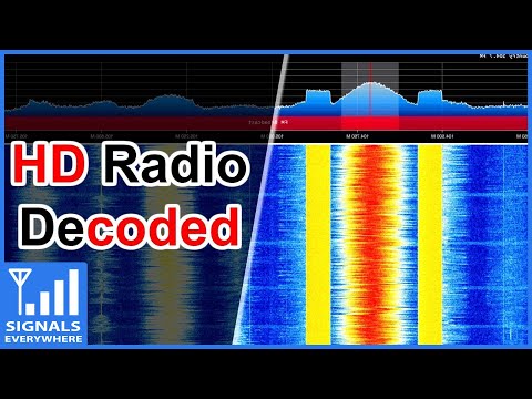
Corrosive (KR0SIV) from the SignalsEverywhere YouTube channel has uploaded a new video that explains and shows HD radio being decoded with an RTL-SDR.
If you are in the USA, you might recognize HD (Hybrid Digital) Radio (aka NRSC-5) signals as the rectangular looking bars on the frequency spectrum that surround common broadcast FM radio signals. These signals only exist in the USA and they carry digital audio data which can be received by special HD Radio receivers. Back in June 2017 we posted about how [Theori] was able to piece together a full HD Radio software audio decoder that works in real time. Later developments saw additional data such as traffic data and weather info extracted from HD Radio too.
Corrosive's video also shows a comparison between analog and HD Radio audio. We note that the "HD" doesn't stand for high definition, so audio quality is not really better than the analog stream. He also notes that the HD Radio data stream can contain multiple audio channels, and often they are not the same as the analog station it surrounds. One example he shows is a Simulcast AM radio station being rebroadcast via HD Radio.
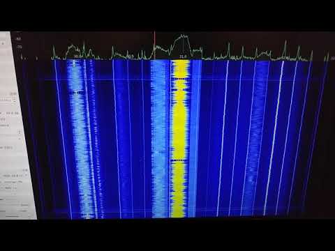
Over on YouTube user Tech Addict Attic has uploaded a video demonstrating what lightning strikes look like on the radio spectrum. To receive the pulses he uses an RTL-SDR and a simple wire antenna located on his roof. He notes that the pulses show up at HF frequencies, and continue all the way up to the broadcast FM band and above.
When lightning strikes it emits a wideband RF pulse that can be detected several miles away by radios. On a software defined radio spectrum display the pulse shows up as a quick horizontal blip. Detecting this blip is how lightning detection websites like blitzortung.org work, although they use their own radio hardware.
In the past we posted about another user who also demonstrated lightning pulses using his RTL-SDR V3.
It is well known that almost all electronic devices unintentionally emit unique spurious RF signals when in operation. By using an SDR like an RTL-SDR to record the spectra from electronic devices, it's possible to build up a database of known emissions. We can then detect when an electronic device is active by comparing the live spectrum to spectra stored in the database.
In a previous post we covered Disney's EM sense which is an experimental smart watch that automatically detects what electronic device the wearer is touching. With EM Sense they use an RTL-SDR and a database of raw pre-recorded spectrum data. To detect what the wearer is touching the live signal from the RTL-SDR is correlated against the database, and the closest match is returned.
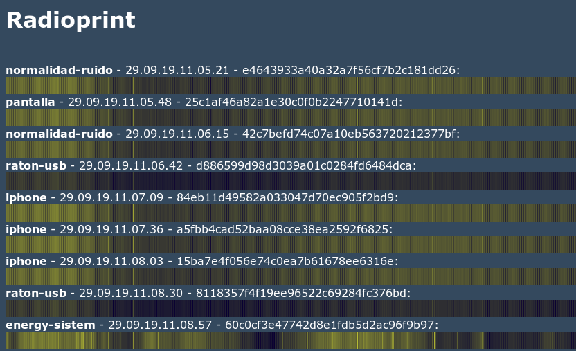
José's script does something very similar, however instead of correlating with raw spectrum data he instead uses the waterfall image that is generated by rtl_power and heatmap.py. The rtl_power program allows an RTL-SDR to scan the frequency spectrum over a wider bandwidth by rapidly scanning ~2.4 MHz chunks of bandwidth at different frequencies. Heatmap.py is a program that turns the scanned data from rtl_power into a heatmap image of the spectrum.
To add an entry to the database, the electronic device is placed 7-8 centimeters away from the RTL-SDR, and a heatmap image recorded between 24 - 921 MHz is saved to disk. This can be repeated for multiple electronic devices. Each image will record the spurious signals from the electronic device, resulting in a unique heatmap image per electronic device.
Once the database has been created, you can then place any of the devices found in the database next to the RTL-SDR, and record a heatmap for 20-30s. That heatmap will then be compared against the images in the database using imagemagick which is an image analysis and manipulation library. The electronic device associated with the closest matching image in the database will be returned.
In his experiments he tested various electronic devices like an iPhone and was able to successfully determine when it was nearby.
Various electronic device spectra waterfall images recorded in the database
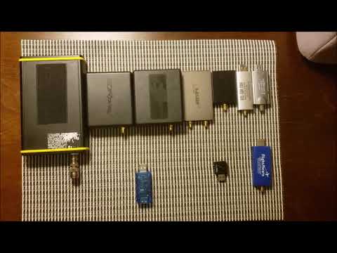
Over on his YouTube channel icholakov has uploaded a video comparing the USB power consumption of various software defined radios. In his tests he uses an inline USB current meter and compares a Perseus, RSP1, RSP1A, Airspy HF+, Airspy HF+ Discovery, RTL V3, Nooelec RTL Mini, Hauppauge 955Q, Flightaware RTL.
If you're only interested in the summary table, then this can be found at 05:49 in the video.
Generally SDRs with better performing tuners and more amplifiers will have higher power requirements, although current consumption can't solely be used to judge performance as some SDRs like the SDRplay make extensive use of filtering to overcome RX performance issues in their tuner. The RTL-SDR V3 and FlightAware dongles have slightly higher current draw compared to the Mini RTL-SDR as they contain an additional HF amplifier and ADS-B amplifier respectively. Lower power consumption may be useful when used with batteries and mobile phones.
2019: Nine SDR Receivers power consumption comparison - how much power does your SDR consume?
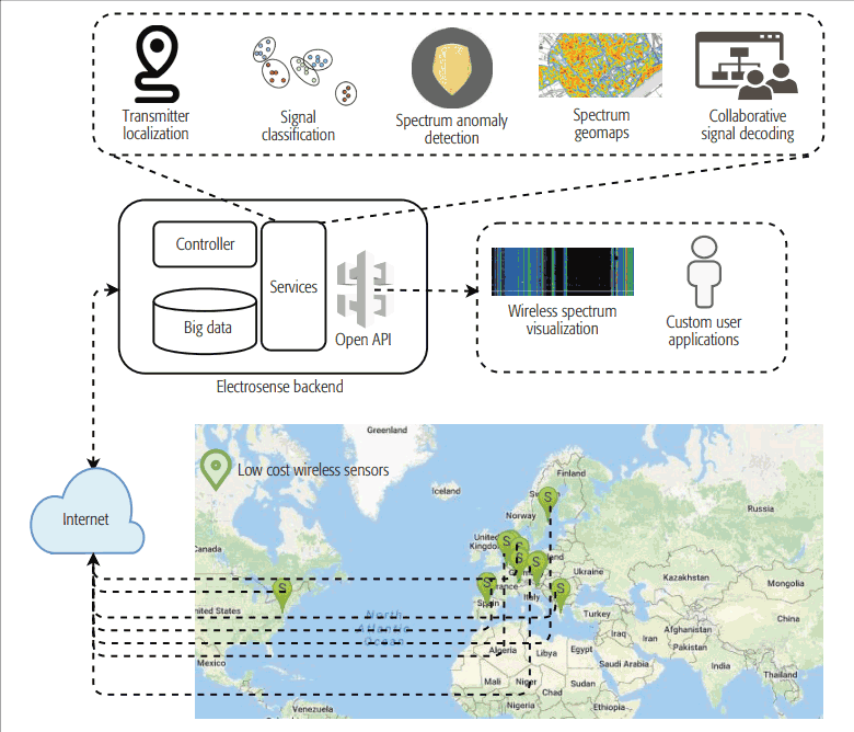
Recently we came across Electrosense which is an interesting open source project that aims to deploy radio spectrum sensors worldwide in order to analyze and understand radio spectrum usage. This information could be extremely valuable in order to make more efficient use of the limited radio spectrum, and for detecting sources of interference and illegal transmissions. The hardware that Electrosense uses consists of just an RTL-SDR, Raspberry Pi, antenna and an optional GPS for time synchronization.
The ElectroSense network is a crowd-sourcing initiative to collect and analyse spectrum data. It uses small radio sensors based on cheap commodity hardware and offers aggregated spectrum information over an open API.
The initiative's goal is to sense the entire spectrum in populated regions of the world and to make the data available in real-time for different kinds of stakeholders which require a deeper knowledge of the actual spectrum usage.
ElectroSense is an open initiative in which everyone can contribute with spectrum measurements and access the collected data.
Overview of the Electrosense network
There are already several spectrum sensing projects in the works by big companies like Google, Microsoft, and IBM, but these only cover a small portion of the spectrum, or use high cost sensing stations limiting their ability to be deployed on a wide scale. Electrosense solves these problems by using low cost RTL-SDRs, and a crowd sourcing paradigm.
At the time of writing there are 103 sensors registered to the Electrosense network, with 23 being online, most of which are in Europe. Once you register an account on their site, you can browse the active sensors. Clicking on the spectrum button for a sensor brings up a live spectrum graph. For example in the screenshot below we access the data from an RTL-SDR + downconverter sensor in Madrid. We're able to see a live wideband 20 MHz to 6 GHz spectrum scan, and graphs of frequency occupancy rates.
Electrosense Active SensorsElectrosense Spectrum Scan and Occupancy Graphs
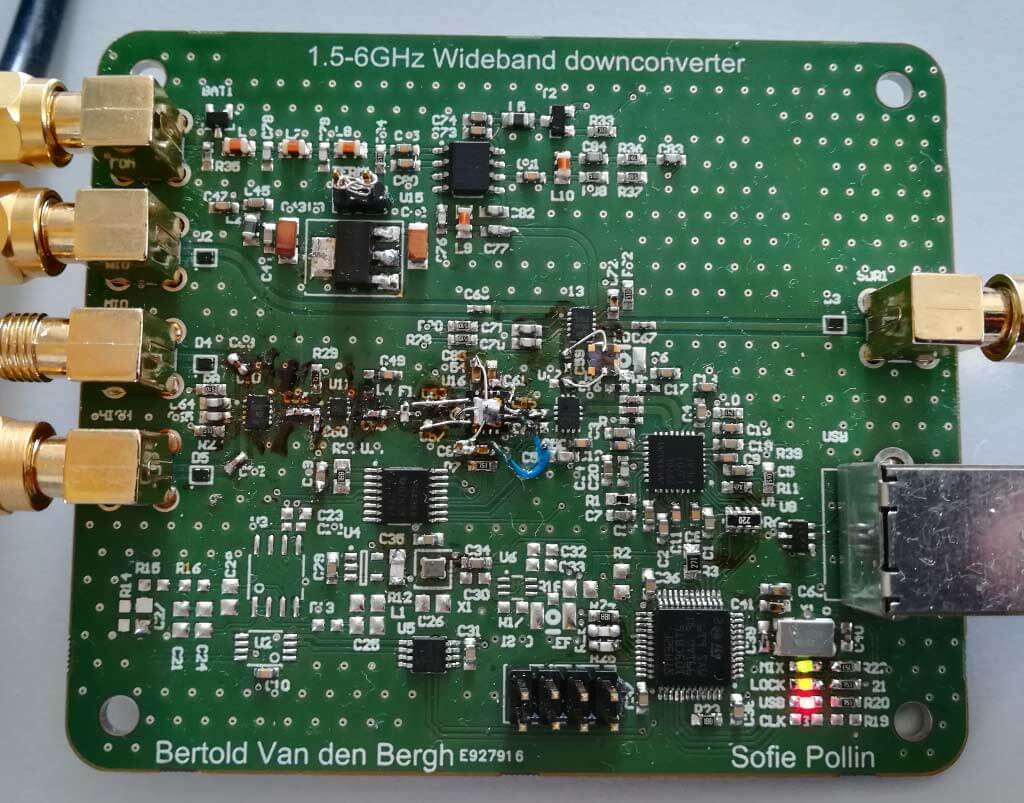
In addition to the standard SDR hardware being used, they've also designed a very interesting open hardware/source DC to 6 GHz up/downconverter board. The board is USB controlled, and switches between the upconverter for the lower HF bands, pass through for receiving DC- 1.6 GHz, and the downconverter for receiving up to 6 GHz. It has a 20 MHz output bandwidth which means that wide band SDRs can also make use of it.
Electrosense Up/Downconverter
The Electrosense website notes that anyone can host a sensor, and if you meet their criteria (permanent internet connection, ethernet connectivity and a low interference location) you can apply for a free kit. If you aren't selected for a free kit, then the Jetvision store based in Europe is selling Electrosense kits that include an RTL-SDR Blog V3, Raspberry Pi 3, power supply, SD card with preinstalled Electrosense software, and either our multipurpose dipole antenna, or a wideband discone with 15m of low loss cable for roof mounting.
The Electrosense team have been working hard on this project and have already published several related papers and a magazine article about the Electrosense network and it's use cases. One interesting paper discusses a method for decoding wideband signals using a network of non-coherent RTL-SDRs. Another paper discusses using using deep learning for automatic signal classification. The full list of publications can be found on their publications page.
If you're interested in this type of crowd sourced spectrum project, then you might also want to take a look at the KiwiSDR which is a networked 0 - 30 MHz SDR. Multiple crowd sourced KiwiSDR's can be used in a TDoA calculation for determining transmitter locations.
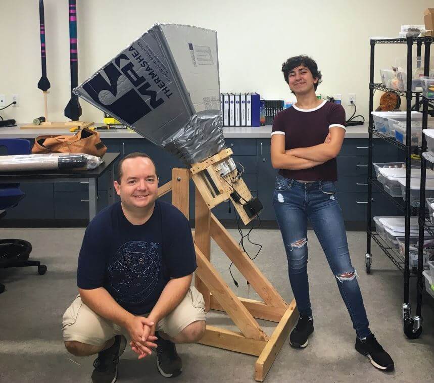
Briefly, their build consists of a horn antenna and reflector designed for the 1,420.4 MHz Hydrogen line frequency. The horn is built out of a few pieces of lumbar, metallic house wall insulation sheets and aluminum tape. The feed is made from a tin can and piece of wire. In terms of radio hardware, they used an Airspy SDR, GPIO labs Hydrogen Line Filter + LNA, and 2x Uputronics Wide band preamps, and a Minicircuits VBF-1445+ filter. For software processing, they used a GNU Radio flowgraph to integrate and record the spectrum.
The results show that they were able to achieve a good hydrogen line peak detection, and they were able to measure the galactic rotation curve doppler shift, and tangent points which prove that we do in fact live in a spiral galaxy.
The Finished Hydrogen Line SDR Based Horn Radio Telescope Antenna