Tagged: rtl-sdr

SignalsEverywhere: Satcom Antennas for L-Band Reception via RTL-SDR + Podcast on the MiTee CubeSat Project

On this episode of SignalsEverywhere on YouTube Corrosive shows off several antennas that can be used for Inmarsat and Iridium satcom reception. His video shows off a commercial Inmarsat branded satlink antenna which is designed to be used on moving ships, a grid dish antenna, a custom QFH iridium antenna made from a repurposed Vaisala radiosonde, a commercial Iridium patch, an older Outernet/Othernet Iridium patch and a custom Iridium patch that Corrosive built himself.

Satcom Antennas for L-Band Reception via RTL SDR

A few days prior Corrosive also released a new episode of his podcast. In this episode he interviewed Derek a student from The University of Michigan who is working on the MiTee CubeSat. The MiTee cubesat is a small experimental satellite that will explore the use of miniaturized electrodynamic tethers for satellite propulsion.

SDR-Makerspace Talk: Evaluation of SDR boards and toolchains

The Software Defined Radio Academy YouTube channel recently uploaded an interesting talk by Alex Csete (creator of the popular GQRX and GPredict applications), and Sheila Christiansen. Their presentation discusses their work with the European Space Agency (ESA), Libre Space Foundation and how they are running SDR Makerspace's that are helping students create and track cubesats. During the talk Alex and Sheila also describe various SDR hardware, and how they test them for their purposes.

SDR Makerspace (https://sdrmaker.space) is a collaboration between the European Space Agency and Libre Space Foundation, with the objective of bringing innovative open-source SDR technologies to space communications.

Space is a complex environment. Attempting to incorporate SDRs into complex subsystems of space missions without sufficient understanding of the technology can add unnecessary risks and uncertainties to the mission. SDR Makerspace aims to bring open-source SDR technology to the space industry, focusing on the practical aspects of satellite communications, so as to reduce such risks.

Makers, open-source hackers, SDR enthusiasts, and researchers are collaborating on SDR hardware and software activities, focusing on rapid prototyping and development of reusable, open-source SDR components for future CubeSat missions.

The collaboration consists of many activities, which are organized into three main elements: development of reusable GNU Radio components, research and development in cutting edge technologies like AI/ML, and testing of SDR hardware and software.

Current activities are presented with a focus on the testing of the hardware and software. An overview of the investigation into the characteristics, such as, performance under realistic conditions, damage by radiation to essential parts, functionality of FPGA toolchains, the SDR-system’s complexity, and accessibility to the open-source community will also be covered.

Alex Csete, OZ9AEC: SDR-Makerspace: Evaluation of SDR boards and toolchains

Weather Satellite NOAA 15 Appears to have Failed (Again)

Back in April 2018 we posted how the NOAA-15 APT weather satellite that many RTL-SDR users enjoy receiving images from was having problems with it's scan motor resulting in image errors. The satellite recovered from that problem, but today the problem appears to be back and in a much worse way now.

Users on Reddit and Twitter have reported bad images coming in from NOAA 15. Over on Reddit u/rtlsdr_is_fun has provided a post showing an example of a corrupted image, and also provided an IQ and Audio file. On his blog [Karsey] has also posted some interesting looking corrupted images that he's received.

Corrupted NOAA-15 Image Received by [Karsey]
Corrupted NOAA-15 Image Received by [Karsey] (See his post for the full sized images)

NASA have put out a statement indicating that yet again it is a problem with the scan motor, and the problem could be permanent.

The NOAA-15 AVHRR Scan Motor current began showing signs of instability at approximately 0400Z on July 23, 2019. At about 0435Z the current rose sharply to about 302mA where it has remained. Scan motor temperature began rising about the same time and is currently steady at ~26M-0C. Black body temperatures dropped sharply at about the same time. The instrument appears to no longer be producing data.
This behavior is consistent with a scan motor stall, but requires further investigation. Options for recovery are limited.

Having been launched in 1998 with a minimum spec of 2 years operation, NOAA-15 has already well outlived it's time and may finally be failing for real. We hope it will recover, but if not we should be thankful that Russian weather satellite Meteor M2-2 is now fully operational and transmitting beautiful high resolution images.

Weather Satellite Meteor M2-2 Now Transmitting Images

Reports from Reddit and Twitter are in that the recently launched Meteor M2-2 weather satellite is now functional and broadcasting images at 137.9 MHz. A few people have noted that the reception quality appears to be better than the older satellite.

Thank you to Happysat whose also provided the following information that can be used to receive the images. It appears that a slightly modified version of LRPTDecoder is required:

This version of LRPTDecoder was used to test/debug OQPSK with Meteor M-N2-1 in 2014, it will work on Meteor M-N2-2.
The ini file attached in the archive is processed manually from s files.
Buttons 72K and 80K respectively for the modes “without interleaving” and “with interleaving”.
Also in the archive there are examples for other modes.

Transmissions on LRPT with a OQPSK Modulation are expected tomorrow on most probably 137.900MHz.

Make sure you have version 1.9 of the Meteor QPSK Plugin running in SDRSharp.
http://rtl-sdr.ru/uploads/download/meteor.zip

Changelog:
Optimized QPSK demodulator, OQPSK signal for receiving current and future Meteor.

For people running Tracking DDE Client Plugin make sure you have the following entries in the scheduler:

METEOR-M2_2

radio_Start
radio_modulation_type<wfm>
radio_center_frequency_Hz<138380050>
radio_frequency_Hz<137900000>
radio_bandwidth_Hz<90000>
OQPSK_demodulator_Start
send_tracking_frequency_On

Edit to your path! for MeteorGIS Custom ini file start_programm_Path<C:\Meteor\MeteorGIS\MeteorGIS.exe>

Edit to your path! for MeteorGIS Custom ini file start_programm_Path<C:\Meteor\MeteorGIS\MeteorGIS_M_N2-2.bat>

Edit to your path! Without MeteorGIS start_programm_Path<C:\AMIGOS\run.bat>

send_Tracking_Frequency_Off
OQPSK_demodulator_Stop
radio_Stop

Download:

https://cloud.mail.ru/public/2Se9/9bj36m6AP

Mirror:

http://happysat.nl/2015.3.20.15.zip

Спасибо Олегу, Нцомз и Роскосмосу!

Happysat

PICTOR: An Open Source Low Cost Radio Telescope based on RTL-SDR

PICTOR is an open source and open hardware radio telescope that aims to promote radio astronomy on a budget. It consists of a 1.5 meter parabolic dish antenna, 1420 MHz feedhorn, a two stage low noise amplifier (LNA), high pass filter, and from what we gather, an RTL-SDR. Future designs may also use higher bandwidth SDRs. Currently there doesn't seem to be much information about the build and exact components used in their design, but we're hoping that those details will come in time.

The radio telescope allows a user to measure hydrogen line emissions from our galaxy. Hydrogen atoms randomly emit photons at a wavelength of 21cm (1420.4058 MHz). The emissions themselves are very rare, but since our galaxy is full of hydrogen atoms the aggregate effect is that a radio telescope can detect a power spike at 21cm. If the telescope points to within the plane of our galaxy (the milky way), the spike becomes significantly more powerful since our galaxy contains more hydrogen than the space between galaxies. Radio astronomers are able to use this information to determine the shape and rotational speed of our own galaxy.

PICTOR also has a very interesting web based interface which can be used to let users from anywhere in the world access the telescope and log an observation. The first PICTOR telescope is currently online and observations can be created simply by going to their website, and clicking on the "Observe" link. Users can then enter the frequency and other parameters for their observation, and the resulting graph will be emailed to you after the observation. The software source is available on their GitHub page, and is based on a GNU Radio flowgraph and Python plot script.

For more information about PICTOR, logging an observation, and radio astronomy in general, we recommend checking out their PDF guide. We test ran a short observation at the hydrogen line frequency, and we received a graph with the hydrogen line peak clearly visible (spliced in to the photo below). We note that the wavy shape is due the to shape of the filters they used.

PICTOR Radio Telescope

A Low Cost 2.4 GHz Downconverter from off the Shelf Dev Boards

Over on GitHub Ian Wraith has released his design and microcontroller code for a low cost 2.4 GHz downconverter circuit. A downconverter is a hardware device that shifts the signals that it receives into a lower frequency band. This is useful in the case of RTL-SDRs and Airspy SDRs, as their maximum frequency range is only 1.7 GHz. Ian's 2.4 GHz downconverter reduces those 2.4 GHz signals down to 1 GHz, which can then be received with his Airspy.

Rather than designing a circuit from scratch, Ian's design makes use of several very cheap Chinese evaluation/development boards that he found on eBay. It costs of a mixer board, oscillator board, and an STM32 development board for controlling the oscillator board via SPI. The whole set of hardware cost him less than £30 (~37 USD).

After spending some time working through the difficulties in programming the SPI interface on the STM32 board, he was able to get the downconverter circuit fully working. He notes that he's been able to receive WiFi, Zigbee, Bluetooth and ISM band signals at 2.4 GHz, as well as 3G and 4G cellular signals at 2.6 GHz.

Ian Wraith's Downconverter consisting of three off the shelf cheap Chinese eBay boards.

SignalsEverywhere: Improving HF Reception with Impedance Matching

This week on the SignalsEverywhere YouTube channel host Corrosive explores why impedance matching matters when trying to obtain the best reception possible. To do this he reviews the NooElec 1:9 Balun, which is designed to convert the (roughly) 450 Ohm impedance of a long wire antenna or ladder line dipole back down to 50 Ohms, which is the standard impedance that an SDR expects. Small amounts of impedance mismatch are negligible for RX, but larger mismatches can result in poor reception.

SDR Nooelec 1:9 Balun | Why Impedance Matters in Radio

Upcoming KerberosSDR Software Updates: Automatically Estimate TX Location and Navigate There

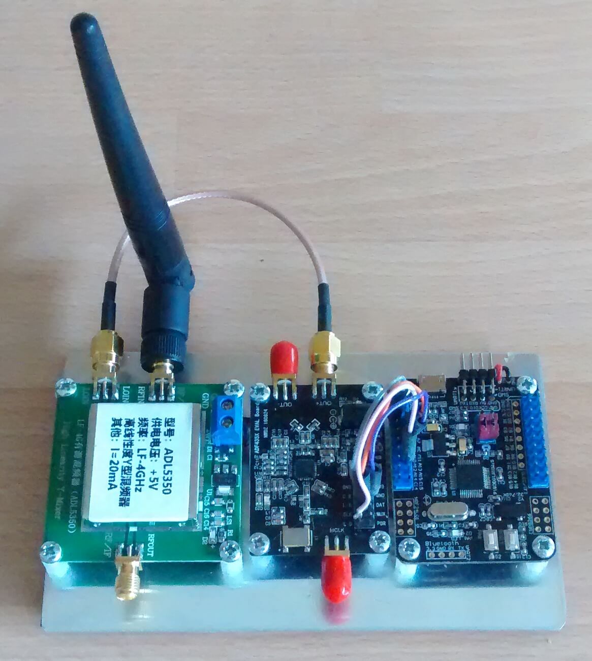
KerberosSDR is our 4x Coherent RTL-SDR that we've developed together with Othernet. It can be used for tasks such as direction finding and passive radar. KerberosSDR was successfully crowdfunded over on Indiegogo, and the first batch has already been shipped. Currently we are taking discounted pre-orders for a second production batch on Indiegogo. Please note that the discounted pricing will expire when we ship, which according to the manufacturing schedule should be next month, so please get in quick if you're interested!

If you'd like to back the KerberosSDR project and purchase a unit, please see our Indiegogo page.

Below are some recent updates to the project:

Android App Software Improvements

The Android App allows a KerberosSDR user to drive around in a car, collecting angle of arrival data for a signal. Driving around and collecting multiple data points solves the multipath issue. In a single location it is possible for a signal's direction of arrival to be skewed or incorrect as it can bounce off multiple surfaces and appear to be arriving from a wrong direction. If we collect data from many locations, we can average out the multipath.

We've recently been working on improvements to the direction finding capabilities of the KerberosSDR, and in particular to our free Android App which records and plots data from the KerberosSDR server. We are still testing and finalizing these new features, but hope to release the updated app before the end of this month.

Recently added features to the app include:

  • Added the ability to determine the estimated location of a transmitter, providing there has been sufficient data collected.
  • Added a heatmap grid of the collected data which can be used to determine where most angle lines cross. Can take into account RF power data too.
  • Added the ability for the software to automatically navigate you to the estimated TX location via MapBox GPS turn by turn navigation.

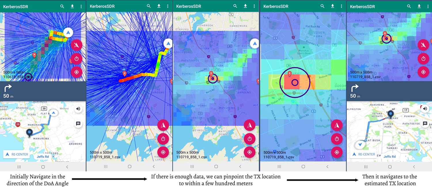
Bellow are screenshots showing some of the new features. In this experiment we located an 858 MHz TETRA transmit tower. Initially the app will navigate you to the edge of the grid, in the direction that most DoA lines are pointing to. When there is sufficient data to be able to confidently pinpoint the TX location, it will begin navigating you to the estimated location. In the screenshots the placemarker represents the known location of the transmitter, and the circles indicate the location estimated from direction finding.

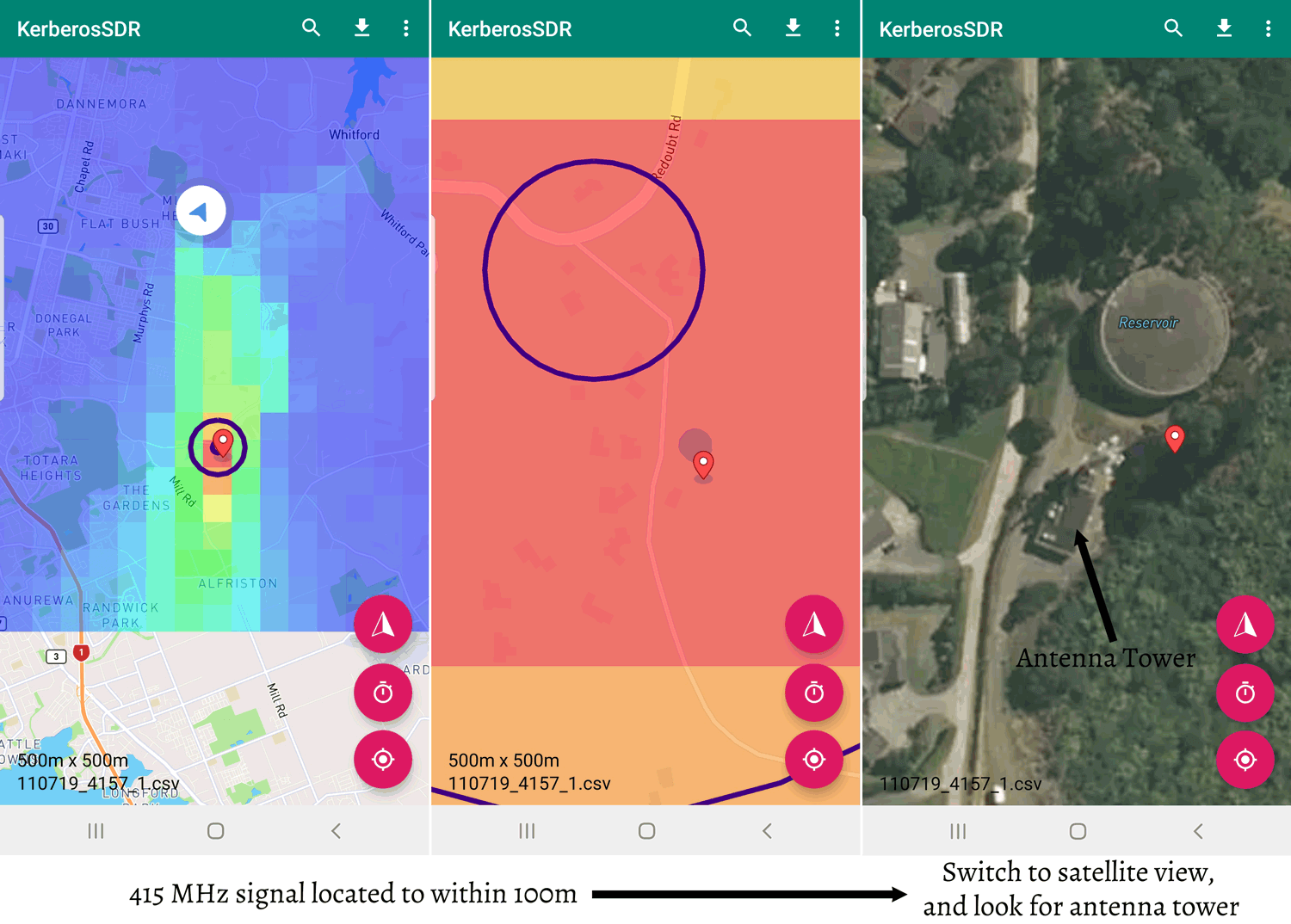
Below is screenshots from a 415 MHz DMR tower that we located with KerberosSDR. The antenna array was purposely kept small, with a diameter of only 12cm. Even with the small antenna array we were able to pinpoint the transmitter down to about 100 - 200 meters.

The app should also now be able to handle intermittent signals, via a squelch filtering function, although this has not been fully tested yet.

In order to navigate you must have a 3G/4G data plan on your phone, and your phone must have the ability to create a WiFi hotspot. The KerberosSDR server running on a Pi 3 or similar will then automatically connect to a WiFi hotspot named "KerberosSDR" running on your phone and provide data to the app via WiFi.

Batch 2 Manufacturing Updates

Batch 2 production is in full swing, and at the moment we're expecting completion by mid August. This batch will ship directly from China, so we should be able to ship them off fairly quickly rather than needing to first wait for them to arrive in the USA.

Magnetic Whip Antennas

We have been disappointed that it has been difficult to find low cost but good quality magnetic whip antennas to use with KerberosSDR and vehicles. The quality of antennas used in direction finding equipment can matter, as any signals leaking into the coax, or radiation pattern skew can affect results. We are working on sourcing some high quality magnetic whip antennas that have good ground coupling. These will be sold at a reasonable price on our store.

Future Updates

We are still working on improving the server software further too and future updates will include things like the ability to notch out unwanted signals during phase calibration, a simplified DoA set up wizard, an improved buffering scheme so that additional data and processing gain can be applied, and more.

The Raspberry Pi 4 looks to be an excellent candidate to be used with the KerberosSDR. We will begin releasing ready to use images for the Pi 4 in the future.

Thanks!

Every sale of a KerberosSDR helps fund further developments to the software and possible future iterations of the hardware. So we'd like to thank all backers once again!