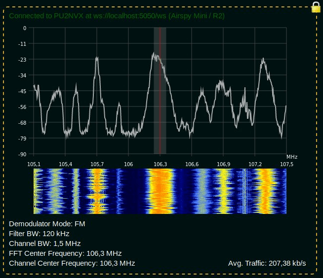
Over the last few months Lucas Teske (author of the Open Satellite Project) has been working on a piece of software called "SegDSP". The idea appears to create a web GUI based SDR receiver for SpyServer streams which can be used to create a cloud of channel demodulators, essentially segmenting the DSP computation burden over multiple computers.
SpyServer is a SDR server application that is compatible with Airspy products and RTL-SDRs. It allows you to connect to these SDRs remotely over a network or internet connection. The SDR server computer sends the radio IQ data over the network allowing you to perform processing remotely. A major advantage of SpyServer compared to other SDR server applications is that it only sends the raw IQ data for the portion of the spectrum that you're interested in which can save a lot of bandwidth.
One key application that Lucas envisions for SegDSP is using it with cloud clusters of single board computers (SBC) like the Raspberry Pi 3. The philosophy is that there will be specific roles for each SBC machine. For example you might have some SDR machines running SpyServers, some processing machines for demodulating and decoding multiple channels, and a storage machine for recording data. Then you can dynamically spawn / despawn workers when needed (for example only spawning a machine when a LEO satellite with data to decode passes over).
SegDSP development is still in the early stages, and appears to only have the web GUI set up at the moment with a few demodulators. But keep an eye on his Twitter @lucasteske for updates too. Lucas also did a talk at the last CyberSpectrum meetup. His talk can be found at 1:30:00 in the recording.
Thanks to Steve K2GOG of The Hudson Valley Digital Network (HVDN) for submitting his post on how to create a wireless display for Pi-Star. Pi-Star is a pre-built Raspberry Pi image for amateur radio users experimenting with digital voice communications like D-STAR and DMR. They write that it can be used for applications such as a "single mode hotspot running simplex providing you with access to the increasing number of Digital Voice networks, [or a] public duplex multimode repeater".
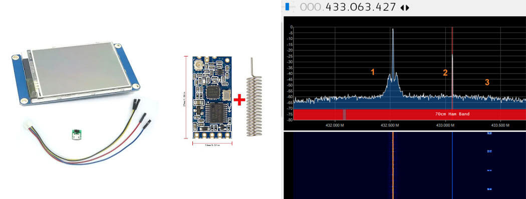
Pi-Star is compatible with serial based LED displays with built in GUIs like the Nextion. The displays are usually connected directly to the Raspberry Pi, but Steve wanted to use the display remotely. To do this he used a simple and inexpensive 70cm band HC-12 wireless serial port adapter. With the wireless adapters connected to the Pi he was able to see the pulses in SDR# via his RTL-SDR to confirm that the wireless serial signal was being sent. He then connected the second wireless adapter to the Nextion display via a few diodes to drop the voltage, and was able to get the display updating as if it was connected directly.
In the post Steve mentions that HVDN are also giving away an HC-12 and RTL-SDR to the first person to submit some progress with this idea.
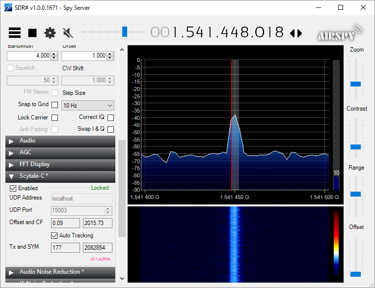
Microp11, the programmer of Scytale-C a standalone Inmarsat decoder has just released a new Inmarsat decoder SDR# plugin. The plugin is currently in the "pre-alpha" stages, so is still missing some functionality and may be buggy. However, it does appear to be functional at this point in time. It can be used with RTL-SDRs, and any other SDR# compatible SDR including units running on remote SpyServers. Microp11 writes:
I ran it with SDR# version v1.0.0.1761.
If it crashes you SDR# I apologize in advance.
The auto-tracking (default on) will alter your SDR# frequency and follow the signal’s CF. When the SNR is very low, please disable it and manually tune the SDR# to try to get the CF as close to 2000 as possible.The demodulator still has plenty ideas of its own.
Use USB mode with 4000 Hz bandwidth.
For now the interface is missing the usual scatter plots.
UDP Address and UDP Port are for sending the decoded frames to the Scytale-C UI.
Offset and CF are the difference from zero error and the CF frequency of the demodulated BPSK signal.
Tx and SYM are the transmitted over UDP frames and SYM is showing the number of demodulated symbols.
A bunch of libraries are attached as extra files. Please be gentle and accept the package as it. Will clean-up in the future.
Use in conjunction with the Scytale-C UI from the archive: “x64-UI1.6-Decoder1.4.zip” (link below)
The magic line is included in the archive: “SDRSharp.ScytaleC-1.0-alpha.zip”
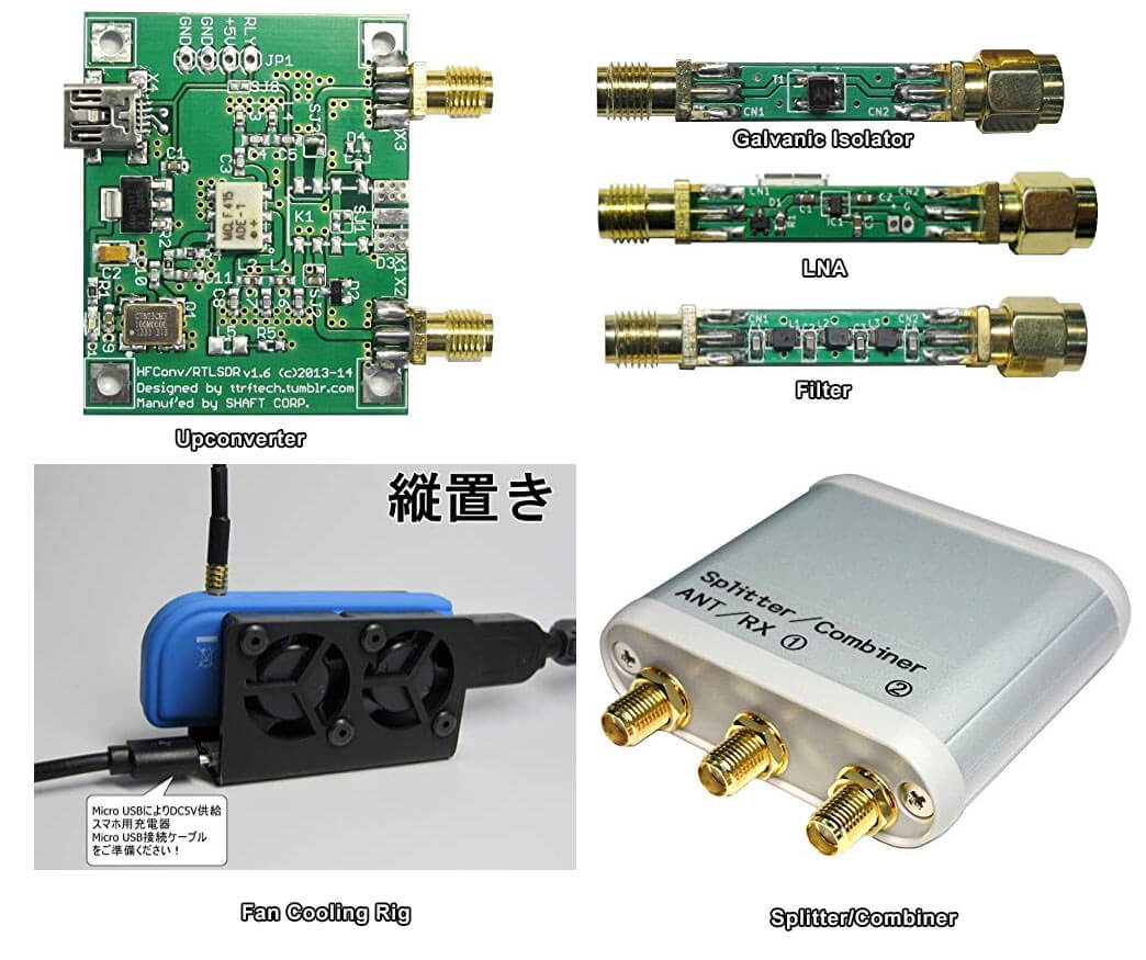
Japan has a strong RTL-SDR scene, with a few small Japanese companies and individuals (including Nobu) selling custom RTL-SDR products on their local Amazon store. Products such as upconverters, galvanic isolators, LNAs, filters, cooling products and more are available. Back in 2015 we reviewed some of these products in a post available here. Since then we've found continued use in particular with the galvanic isolator which helps reduce noise from the computer and nearby electronics at HF frequencies.
Some Custom Japanese RTL-SDR/RF Products available for International Shipping on Amazon.co.jp
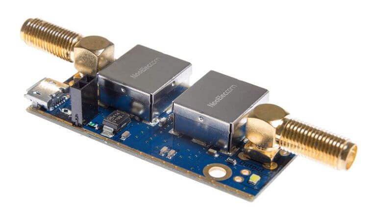
NooElec has just released their new "SAWbird" GOES LNA for sale. This is an LNA and filter combination designed to help receive GOES weather satellite images. On the PCB is a 1688 MHz SAW filter and a low noise amplifier. It can be powered with 3V - 5.5V connected directly or via bias tee. The SAWbird is currently available on Amazon and their store for US$34.95. They also have a version for Inmarsat and Iridium, so make sure you choose the correct one.
GOES 15/16/17 are geosynchronous weather satellites that beam high resolution weather images and data. In particular they send beautiful 'full disk' images which show one side of the entire earth. As GOES satellites are in a geosynchronous orbit, the satellite is in the same position in the sky all the time, so no tracking hardware is required and images can be constantly pulled down throughout the day without having to wait for a satellite to pass over.
However, compared to the more familiar and easier to receive low earth orbit satellites such as NOAA APT and Meteor M2 LRPT, geosynchronous satellites like GOES are quite a bit further away, and transmit at 1.7 GHz. So to receive the signal you'll need a dish antenna that you can accurately point, a good low noise figure LNA and possibly a filter. So setting up a receiver is a bit more difficult when compared to receivers for NOAA and Meteor satellites. The SAWbird should help however, by providing a ready to use LNA+Filter combination.
Over the past few months several testers have already received engineering samples of the SAWbird and have been successful at receiving GOES images. From the results of several experimenters, it appears to be possible to use a cheap 2.4 GHz WiFi grid antenna with some minor modifications as a GOES satellite antenna. Get one with at least a one meter long width and bend the feed as described here or here to tune reception for the 1.7 GHz GOES frequency. Pieter Noordhuis has also shown that it's possible to use an RTL-SDR to receive GOES images, so an entire GOES system can be built on a budget.
NooElec SAWbird LNA + Filter for GOES reception.GOES Full Disk Image of the Earth
Over on GitHub an interesting project that involves using an ultrasound transducer and RTL-SDR to create a low cost 2D ultrasound imager has been uploaded. Ultrasound imagers transmit acoustic sound waves with a transducer at frequencies between 1 - 5 MHz, and then listens for the audio reflections from objects in the audio waves path. This technique is commonly used in the medical field for imaging inside the body without using damaging ionizing radiation like with x-rays.
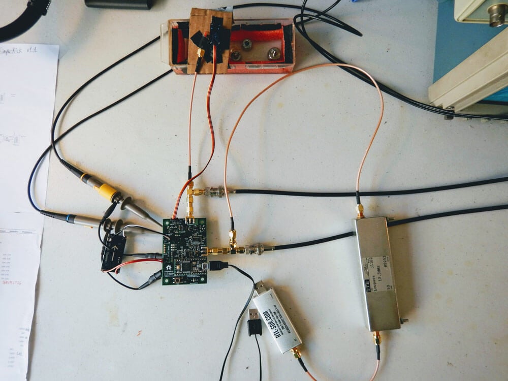
The project by wlmeng11 is based on the open un0rick hardware, which is an open source ultrasound imager. wlmeng11's idea is to simplify and lower the cost of the un0rick hardware by replacing some expensive components like the FPGA and ADC with a computer and RTL-SDR. The simplified hardware is called "SimpleRick" and PCB and firmware files are also available on GitHub.
The rtl_ultrasound setup
Regarding his choice to use SDR and RTL-SDR he writes:
Why SDR?
The analog signal produced by a B-mode ultrasound (ie. 2D imaging) is essentially an Amplitude Modulated (AM) signal. The signal's envelope (ie. amplitude) corresponds to boundary information in the physical media, and the signal's carrier frequency is equal to the resonant frequency of the transducer.
Most ultrasound systems take one of two approaches for data acquistion:
Direct sampling of the ultrasound signal: This method preserves the original signal in the time domain, accomodates any transducer frequency, and offers the best flexibility for post-processing and analysis. Both amplitude and phase information can be extracted the signal, so it is useful for both B-mode and Doppler mode imaging. However, this method requires a high sample rate ADC, as well as high bandwidth and storage for the digital data.
Envelope detection with analog hardware: Perform Amplitude Demodulation (typically with a diode-based rectifier and low pass filter) to yield an envelope signal, then acquire the envelope signal at a lower sample rate. This method reduces the bandwidth and storage requirements for the digital data, but there are a number of drawbacks:
Unless the low pass filter is adjustable, this method cannot accommodate different transducer frequencies.
The non-linearity of the diode may produce harmonic distortion.
All phase information in the signal is lost, rendering it useless for Doppler mode imaging.
It has been demonstrated by Peyton et al that quadrature sampling can be used to reduce bandwidth requirements in an ultrasound imaging system.
It turns out that quadrature modulation is essential to Software Defined Radio (SDR) because any type of amplitude modulation, frequency modulation, phase modulation, or combination of these can be expressed as a special case of quadrature modulation. Therefore, many of the software and hardware techniques used in SDR can be applied to ultrasound imaging.
Why RTL-SDR?
The RTL2832U chip in the RTL-SDR takes a hybrid approach for data acquisition. It employs a high sample rate ADC (28.8 Msps), followed by a software-configurable Digital Down Converter (DDC) that produces IQ data at a lower sample rate (up to 2.56 Msps), thus reducing bandwidth and storage requirements. We can then perform envelope detection in software.
Plus, the RTL-SDR is really cheap (under $25 on Amazon in the United States)! As such, there is a lot of software support and a large community for the RTL-SDR.
With a few software tweaks, it should be possible to substitute the RTL-SDR with a more expensive SDR (eg. AirSpy HF+, LimeSDR) for use cases that require better ADC resolution and SNR.
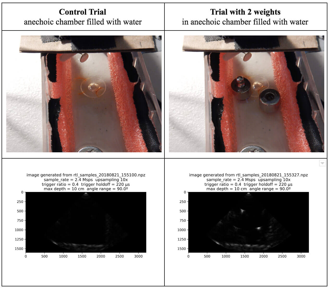
Some of his test results are available in his August 21 writeup. His test involves a pseudo-anechoic chamber with some steel balls to reflect the ultrasound wave. The ultrasound transducer is swept through the chamber using a servo. The results so far have been successful in reliably and repeatedly resolving imaging on objects that are about 1 cm in size.
rtl_ultrasound results
If you're interested in the combination of acoustic transducers and SDRs, then this previous post shows using a piezo to detect ultrasound echolocation sounds from bats.
Hackaday's Hack Chats are a weekly live community chat session where some knowledgeable guests are brought in to chat with the audience. This weeks upcoming chat on Friday is all about GNU Radio, a block based programming language that is commonly used with SDRs like the RTL-SDR. They write:
Our guests for this week’s Hack Chat will be Derek Kozel and Nate Temple, officers of the GNU Radio project. They’re also organizers of this year’s GNU Radio Conference. Also joining in on the Hack Chat will be Martin Braun, community manager, PyBOMBS maintainer, and GNU Radio Foundation officer.
GNU Radio is perhaps the most important bit of any software defined radio toolchain. This is the software that provides signal processing blocks to implement software defined radios. GNU radio is how you take a TV tuner USB dongle and pull images from satellites. You can use it for simulation, and GNU Radio is widely used by hobbyists, academics, and by people in industry.
The Hack Chat starts on Friday August 31, 2018 at noon PDT. You can leave a comment for the Hack Chat now by leaving a comment on the event page.
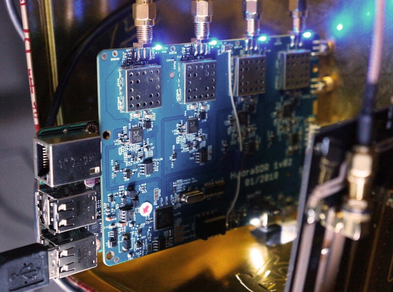
KerberosSDR (formerly HydraSDR) is our upcoming 4-input coherent RTL-SDR. It's designed for coherent applications like RF direction finding, passive radar, beam forming and more, but can also be used as a standard 4-channel SDR for monitoring multiple frequencies. In this post we demonstrate the direction finding application running on the TinkerBoard.
Reminder: If you have any interest in KerberosSDR, please sign up to our KerberosSDR mailing list. Subscribers to this list will be the first to know when KerberosSDR goes on preorder, and the first 100 sales will receive a discounted price.
KerberosSDR Updates
This week we've managed to get the KerberosSDR demo software made by Tamás Peto functioning on a TinkerBoard. The TinkerBoard is a US$60 single board computer. It's similar to a Raspberry Pi 3, but more powerful. We've also tested the app running on the Raspberry Pi 3 and Odroid XU4. The Pi 3 is capable of running the software but it is a little slow, and the Odroid XU4 is a little faster than the TinkerBoard. In the future we hope to further optimize the code so even Raspberry Pi 3's will be smooth.
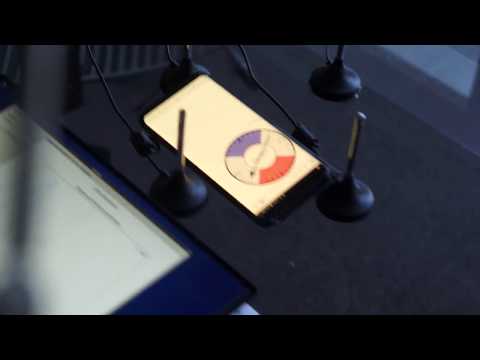
In the video below we used a circular array of four whip antennas connected to KerberosSDR. The TinkerBoard is connected to KerberosSDR and is set up to generate a WiFi hotspot, which we connect to with an Android phone and a Windows laptop. The Windows laptop connects to the TinkerBoard's desktop via VNC, and the Android phone receives an HTML/JavaScript based compass display via an Apache server running on the Tinkerboard. With this setup we can wirelessly control and view information from KerberosSDR and the TinkerBoard.
We've also tested the KerberosSDR system on a real signal, and have found it to work as expected. More demo's of that coming later.